Member with skin

a skin and member technology, applied in the field of members with skin, can solve the problems of affecting the decorativeness of the conventional member with skin, the peripheral-end skin portion might be difficult to cover the substrate, and the assembly worker or the assembly robot is tired and difficult to operate, so as to achieve better decorativeness, better decorativeness, and better positioning of the skin with respect to the substrate

Inactive Publication Date: 2013-02-19
TOYODA GOSEI CO LTD
View PDF3 Cites 0 Cited by
  • Summary
  • Abstract
  • Description
  • Claims
  • Application Information

AI Technical Summary

Benefits of technology

[0009]The present invention has been developed in view of the aforementioned circumstances. It is therefore an object of the present invention to provide a member with skin that exhibits better decorativeness.

Problems solved by technology

Moreover, it is a tiresome and difficult operation for an assembly worker or robot to cover the substrate 101 with the skin 105 while positioning the peripheral-end skin portion 160 highly accurately with respect to the substrate 101.
In addition, the decorativeness of the conventional member with skin might be impaired by the peripheral-end skin portion 160 that should have been displaced with respect to the substrate 101.

Method used


Image

  • Member with skin
  • Member with skin
  • Member with skin

Examples


examples

[0041]Hereinafter, some of members with skin according to specific examples of the present invention will be described with reference to the accompanying drawings.

example no.1

Example No. 1

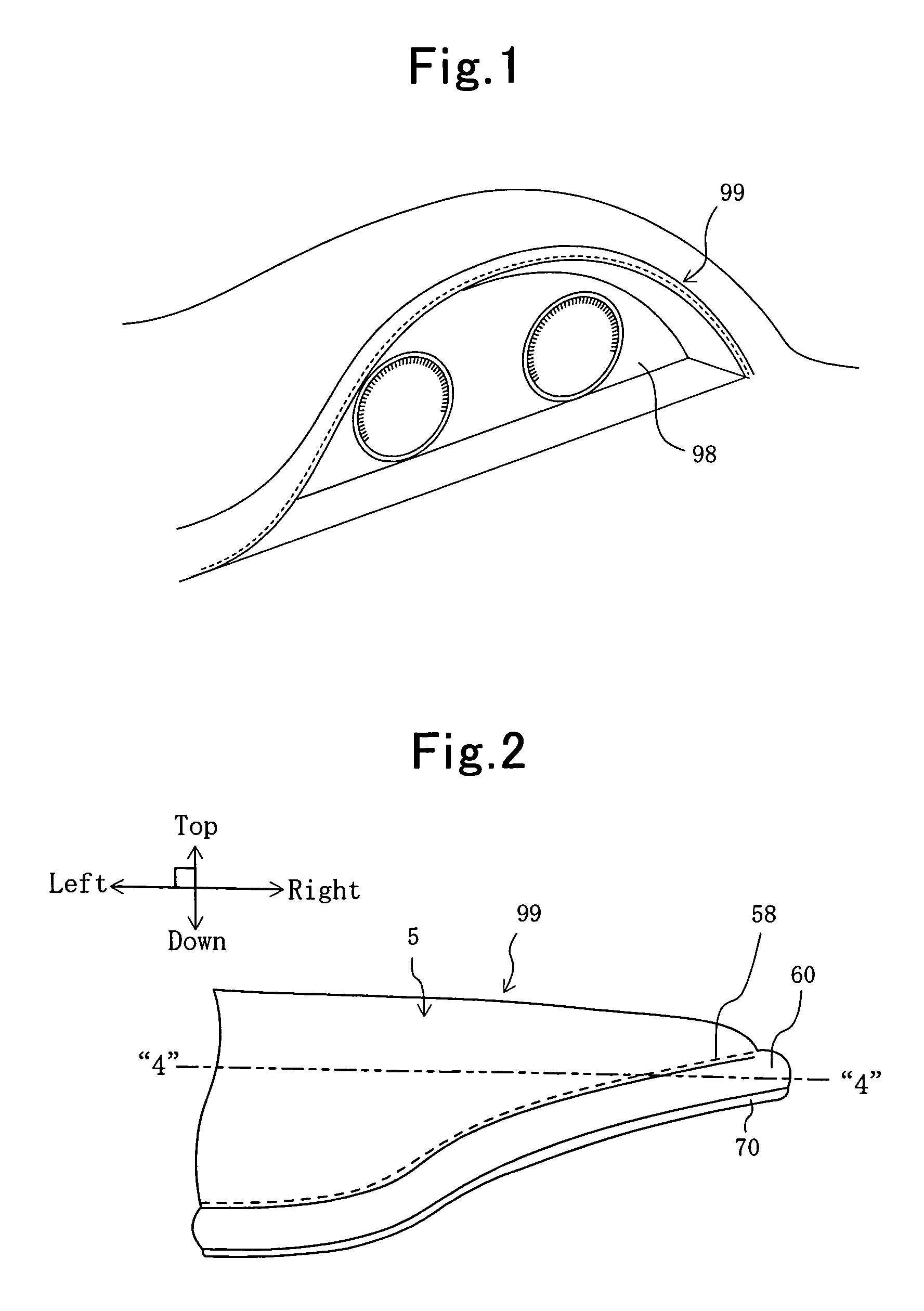
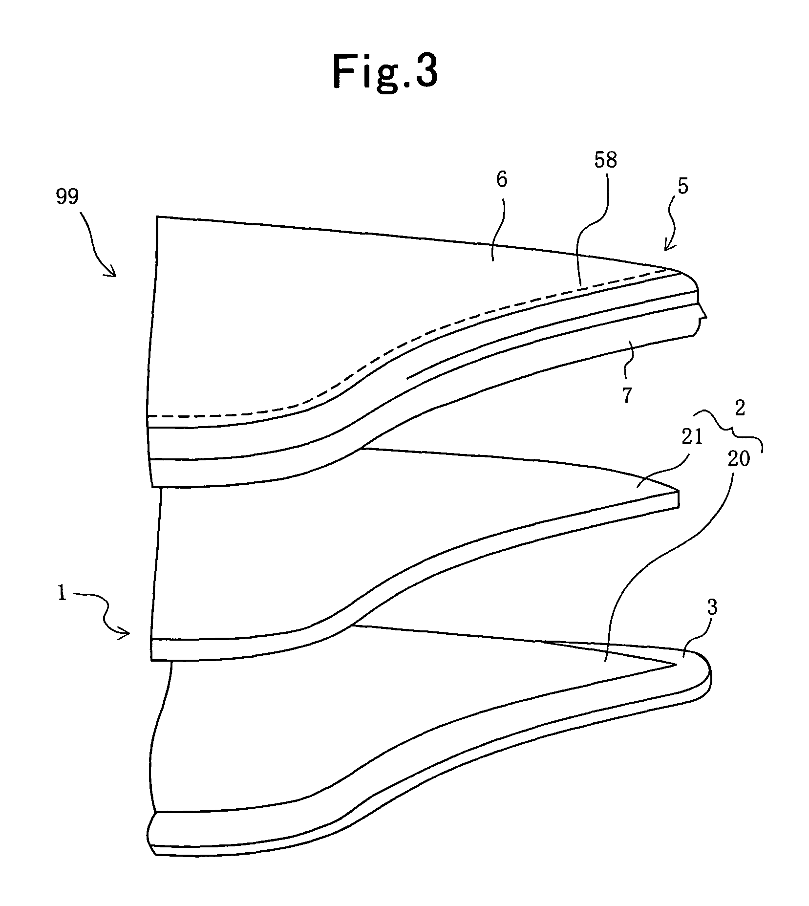
[0042]A member with skin according to Example No. 1 of the present invention makes a meter hood, one of interior component parts for automobile. FIGS. 1 through 4 show explanatory diagrams for illustrating the present member with skin according to Example No. 1. Specifically, FIG. 1 schematically illustrates how the present member with skin according to Example No. 1 appears when it is disposed in vehicle in a perspective diagram. FIG. 2 schematically illustrates a major part of the present member with skin according to Example No. 1 in an enlarged perspective diagram. FIG. 3 schematically illustrates another major part of the present member with skin according to Example No. 1 in an enlarged exploded perspective diagram. FIG. 4 schematically illustrates how the present member with skin according to Example No. 1 appears in a cross-sectional diagram. Note that FIG. 4 shows a cross section of the present member with skin according to Example No. 1 when it is cut at a pos...

example no.2

Example No. 2

[0052]A member with skin according to Example No. 2 of the present invention is identical with the present member 99 with skin according to Example No. 1 other than the following settings: it further comprises a secondary core (namely, an insert or armature) that is made independently of the substrate; and it comprises a second peripheral-end skin portion that covers the secondary core, too. In FIG. 5, the present member with skin according to Example No. 2 is illustrated schematically in a cross-sectional diagram that shows how the present member with skin appears when it is cut at the same position as that is designated with the “4”-“4” chain double-dashed line in FIG. 2.

[0053]In addition to the component elements of the present member 99 with skin according to Example No. 1, the present member 99 with skin according to Example No. 2 further comprises a secondary core 9. The secondary core 9 is made of polypropylene (or PP), and is formed as a cylindrical shape substa...


PUM

PropertyMeasurementUnit
thicknessaaaaaaaaaa
floating heightaaaaaaaaaa
floating widthaaaaaaaaaa

Abstract

A member with skin includes a substrate, and a skin. The substrate includes a body, and a core. The skin includes a first skin segment, and a second skin segment. The body and core make a rear side-face section, which is disposed beneath a rear face of the core, within a side face in the substrate. The member further includes a stitching allowance, which is disposed to face the rear side-face section in the substrate, between the first skin segment and the second skin segment. The first skin segment covers a front face of the body, and a front face of the core. The second skin segment covers a rear face of the body. The member further includes ornamental stitches that are disposed at a boundary between a part of the first skin segment covering the body and another part of the first skin segment covering the core.

Description

INCORPORATION BY REFERENCE[0001]The present invention is based on Japanese Patent Application No. 2009-222,343, filed on Sep. 28, 2009, the entire contents of which are incorporated herein by reference.BACKGROUND OF THE INVENTION[0002]1. Field of the Invention[0003]The present invention relates to a member with skin that comprises a substrate, and a skin covering the substrate.[0004]2. Description of the Related Art[0005]Many members with skin have been known heretofore, members which comprise a substrate, and a skin that covers the substrate. For example, Japanese Unexamined Patent Publication (KOKAI) Gazette No. 2008-94,126, and Japanese Unexamined Patent Publication (KOKAI) Gazette No. 2008-100,453 disclose some of conventional members with skin, respectively. FIG. 6 is an enlarged perspective view for illustrating a major part of one of the conventional members with skin. FIG. 7 is a cross-sectional diagram for illustrating how the conventional member with skin being shown in FI...

Claims


Application Information

Patent Timeline
Patent Type & Authority Patents(United States)
IPC IPC(8): B32B3/04
CPCB32B27/08Y10T428/24223Y10T428/24215Y10T428/24198Y10T428/24033B32B3/04B32B3/263B32B3/28B32B5/18B32B9/025B32B9/045B32B9/046B32B27/065B32B27/302B32B27/308B32B27/32B32B27/365B32B2250/44B32B2266/0278B32B2605/003
Inventor FUKUI, NAOYUKIIMURA, KIMITOSHISAKAKIBARA, YASUHIRO
Owner TOYODA GOSEI CO LTD
Why Eureka
Try Eureka