Eureka AIR delivers breakthrough ideas for toughest innovation challenges, trusted by R&D personnel around the world.

Wound treatment device

a treatment device and wound technology, applied in the direction of knitting, catheters, ornamental textile articles, etc., can solve the problems of clogging, inserts need to be changed, and the effect of weakening the vacuum

Inactive Publication Date: 2013-02-19
T J SMITH & NEPHEW
View PDF27 Cites 120 Cited by
  • Summary
  • Abstract
  • Description
  • Claims
  • Application Information

AI Technical Summary

Benefits of technology

The invention is a wound insert made of a planar textile spacer fabric that is placed into a wound to improve wound treatment and healing. The fabric has a flexible, compressible, and high displacement under slight pressure, making it ideal for use as a wound insert. The fabric has a biocompatible surface that comes in contact with the wound tissue, allowing tissue fluids to pass through while preventing the growth of wound tissue. The fabric is designed to be placed into the wound and a vacuum is created to compress the fabric and stimulate new tissue growth. The fabric can also be coated with a biocompatible material or have a support layer for added strength. The technical effects of this invention include improved wound treatment and healing through the use of a flexible, compressible, and high-displacement wound insert.

Problems solved by technology

The small-pored foam may become clogged however, for example, due to a clot, so that the vacuum effect weakens and accordingly the wound insert needs to be changed.
The problem of clogging may also appear in this situation.
Tissue fluids which flow out of the wound into the interspace through the porous surface layer can be suctioned out, which makes clog formation practically impossible due to the open area space.
Secondly, the vacuum-effect is also exercised on the wound tissue, whereby tractive forces act on the tissue cells.

Method used


Image

  • Wound treatment device
  • Wound treatment device
  • Wound treatment device

Examples


Embodiment Construction

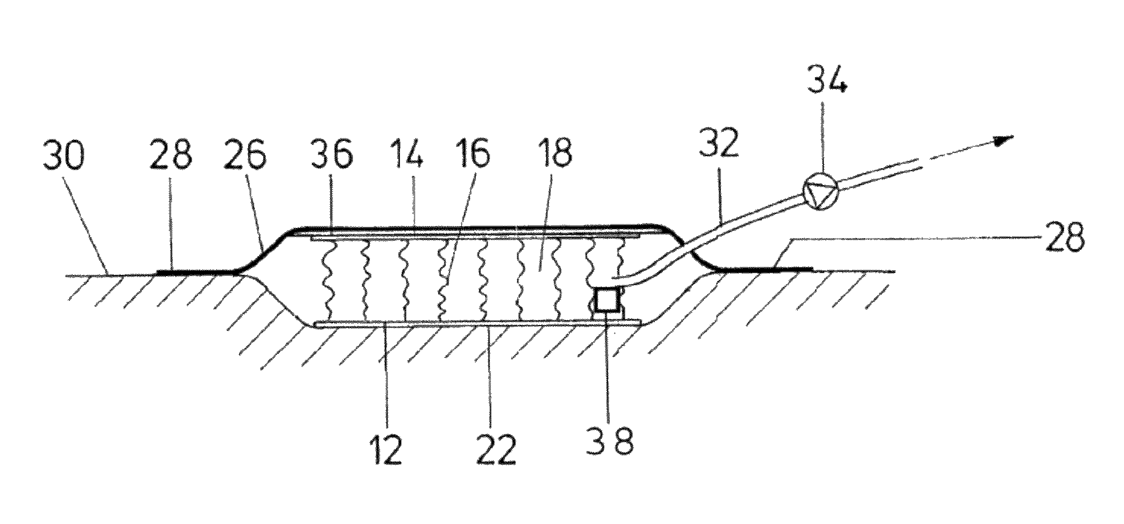
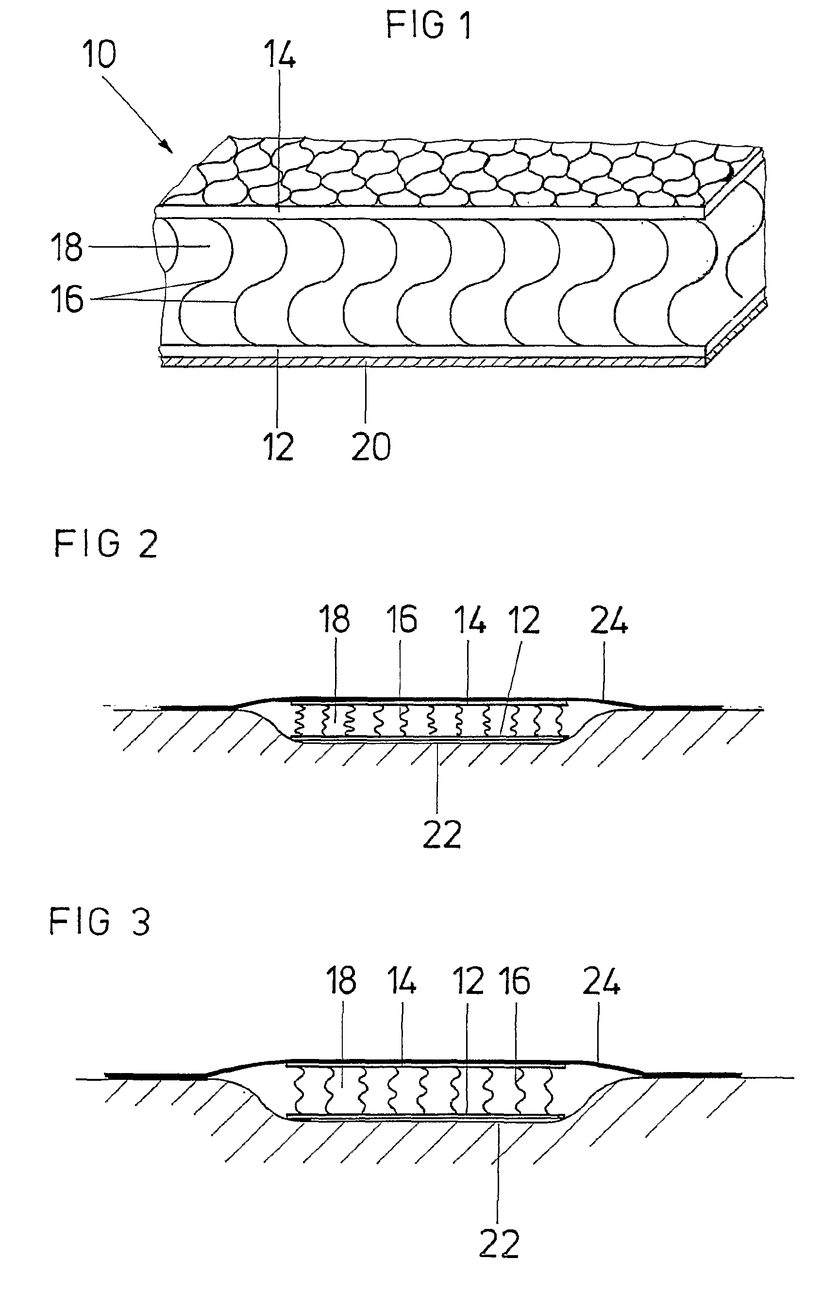
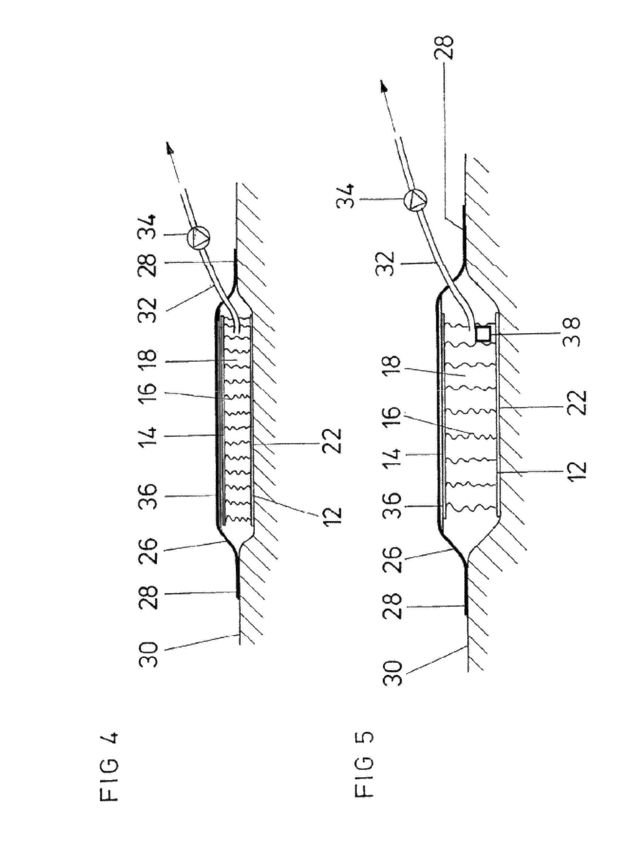
[0034]According to the invention, wound insert 10, whose construction is schematically illustrated in one embodiment in FIG. 1, is used. Wound insert 10 consists of a planar textile spacer fabric, and is cut into adequate size according to the respective demands of the wound that is to be treated. Should the demand arise, the wound insert can also be available in given standard dimensions. The textile spacer fabric exhibits a first surface layer 12 and a second surface layer 14. Surface layer 12 and surface layer 14 are held apart by elastic cushioning spacer filaments 16. Thus, a relatively large interspace 18 is formed between surface layer 12 and surface layer 14. In this interspace 18 are found spacer filaments 16, which exhibit a relatively large mutual separation, so that the interspace 18 in the plane of the wound insert 10 is substantially open and exhibits between the spacer filaments 16 a large free flow-through cross section. Surface layers 12 and 14 can be pressed agains...


PUM


Abstract

A wound treatment device comprises a wound surface contacting plug (10) and a cover (24) for covering the wound surface (22) and the plug (10), wherein said plug (10) consists of a flat textile isolating material comprising at least one first surface layer (12), one second surface layer (14) and one intermediate space (18) arranged between said surface layers (12, 14). At least the first surface layer (12) is provided with a biocompatible surface and a structure which enables a liquid to pass and prevents a wound tissue from growing in said structure. The intermediate space (18) is provided with isolating threads (16) elastically holding the first surface layer (12) and the second surface layer at a certain distance from each other.

Description

CROSS REFERENCE TO RELATED APPLICATION[0001]This application is a §371 National Phase of PCT / EP2005 / 012621, filed Nov. 25, 2005, the entirety of which is hereby incorporated by reference.FIELD OF THE INVENTION[0002]The invention concerns a wound treatment device.BACKGROUND OF THE INVENTION[0003]From EP 0 620 720 B1 it is known that a wound insert, which consists of an open-cell polymer-foam, should be placed on the wound surface. The wound surface and the wound insert are sealed over with a cover that is sealingly secured to the skin surrounding the wound surface. A vacuum can be created under the cover using a suction tube in order to vacuum tissue fluids out of the wound. The polymer-foam exhibits a relatively small pore size in order to prevent in-growth of wound tissue into the wound insert. The small-pored foam may become clogged however, for example, due to a clot, so that the vacuum effect weakens and accordingly the wound insert needs to be changed.[0004]From U.S. Pat. No. 4...

Claims


Application Information

Patent Timeline
IPC IPC(8): A61H7/00A61F13/00A61F15/00A61L15/00A61M5/32A61M5/178A61M1/00
CPCA61F13/00068A61M1/0088D04B21/16A61F2013/00119A61F2013/00174A61F2013/00412A61F2013/00536D10B2403/021A61F2013/00957D10B2509/022A61F2013/0074A61M1/915A61M1/92A61M1/916A61M1/966A61F13/05A61F13/00A61F2/02B32B3/26A61M1/964A61F2013/00131A61M39/24
Inventor FLEISCHMANN, WILHELM
Owner T J SMITH & NEPHEW
Why Eureka
Eureka Blog
Learn More