
True RMS power measurement

a power measurement and root mean square technology, applied in the field of true root mean square (“ rms”) power measurement of signals, can solve the problems of difficult and costly change to the integration time, inability to achieve the change of integration time, and inability to obtain digital outputs with extra circuitry, so as to reduce or simplify the bill of materials, improve the performance of power measurement, and remove the sensitivity of power measurement

Inactive Publication Date: 2013-02-12
SCINTERA NETWORKS
View PDF3 Cites 11 Cited by
  • Summary
  • Abstract
  • Description
  • Claims
  • Application Information

AI Technical Summary

Benefits of technology

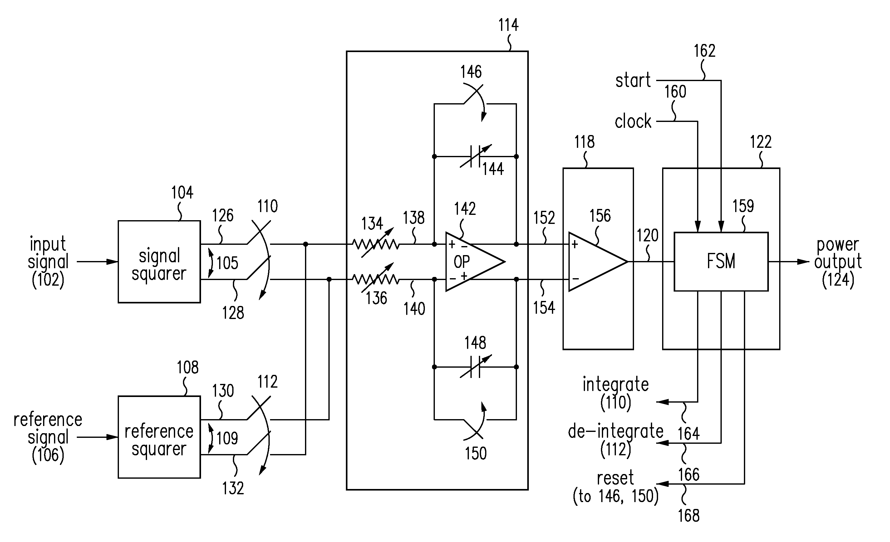
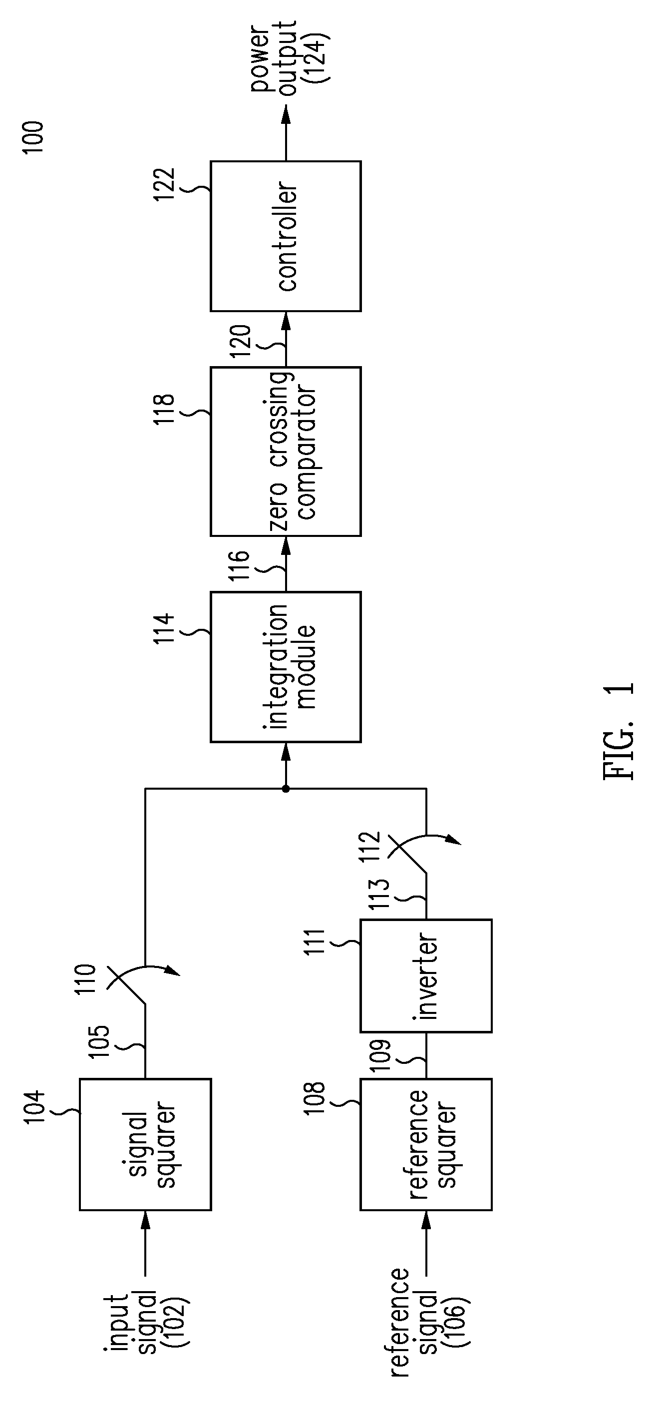
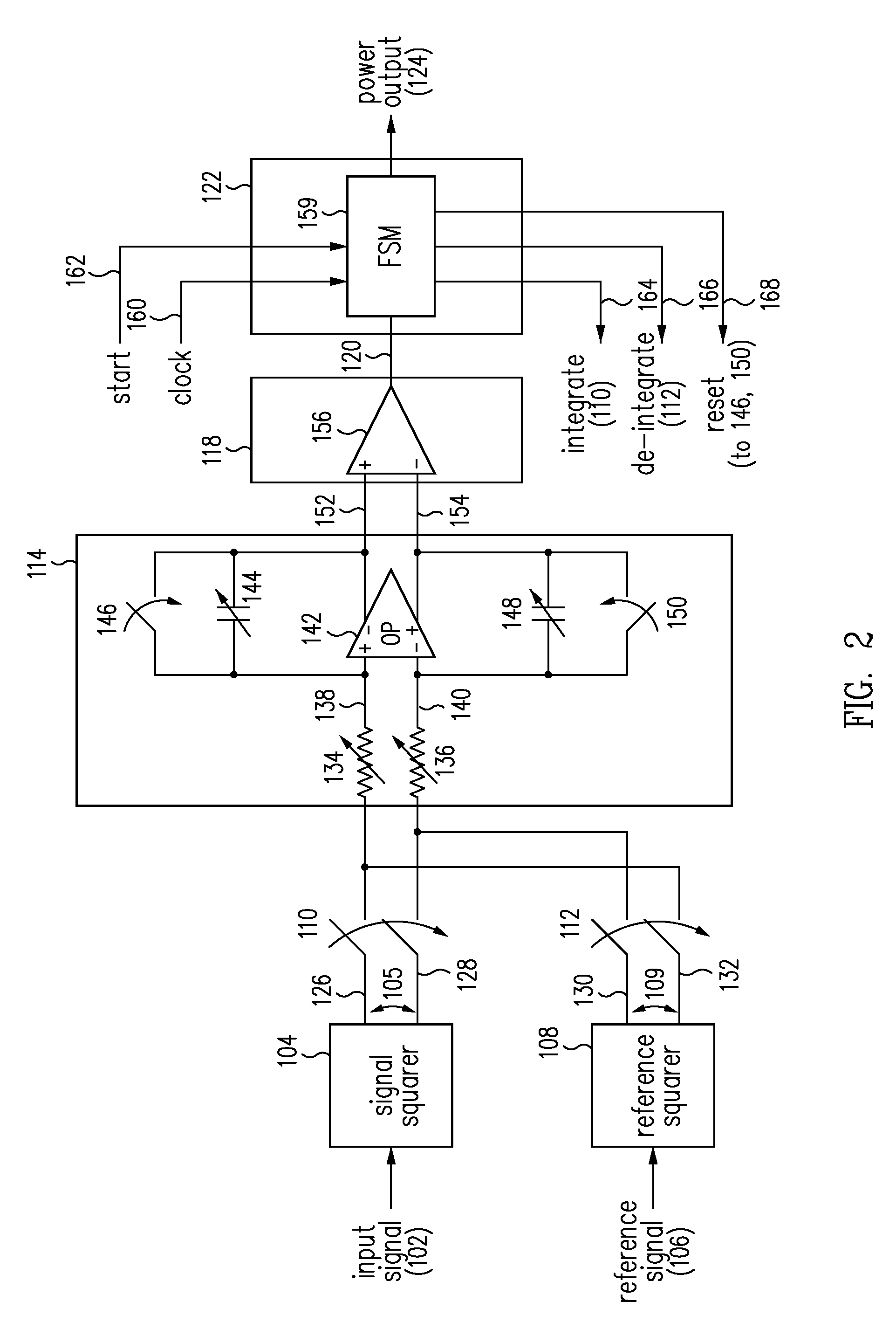
The patent describes a system and method for measuring the average power or root mean square of a signal using analog squarer circuitry and an integrating analog-to-digital converter (ADC). The integrating ADC removes sensitivity to process, voltage, and temperature variations, and can be controlled digitally to accommodate different types of signals. The system also includes a time constant determining integration resistor and capacitor, which simplifies the bill of material, and replica analog power squarer circuits that improve the performance of the power measurement. Although process-dependent mismatches may be present, a calibration procedure can remove them.

Problems solved by technology

In a conventional RMS power measurement device, this measurement accuracy may be limited by the sensitivity of the device to variations in device process, voltage, or temperature (PVT).
However, such a capacitor is often too big to be integrated into the power measurement device, making any change to the integration time difficult and costly.
Furthermore, many power measurement devices generate power measurements as analog signals, so that extra circuitry is needed to obtain digital outputs required for subsequent processing.
Such circuitry not only incurs extra cost but may also be subject to PVT variations, compounding the PVT sensitivity of the power measurement devices.

Method used


Image

  • True RMS power measurement
  • True RMS power measurement
  • True RMS power measurement

Examples


Embodiment Construction

[0019]Systems and methods are provided for measuring power of a signal such that the measured power is insensitive to PVT variations of the measurement systems. In various embodiments, a power measurement system of the present invention includes replica analog squarer circuitries, an integrating ADC, and a controller. A first analog squarer circuitry generates the square of the signal to yield the instantaneous power of the signal. The integrating ADC integrates the instantaneous power of the signal over a programmable integration interval to build up an integrated voltage at the output of the ADC. A second analog squarer circuitry generates the square of a known reference signal. After the integration interval, the integrating ADC receives the square of the reference signal to de-integrate the integrated voltage over a de-integration interval. The de-integration interval is measured as the time it takes for the integrated voltage to completely de-integrate. The controller digitally...


PUM


Abstract

Systems and methods are provided for power measurement of signals such that the power measurement is insensitive to PVT variations of the measurement systems. A power measurement system includes an analog squarer circuitry, an integrating ADC, and a controller. The squarer circuitry calculates the power of a signal whose power is to be measured while the integrating ADC integrates the calculated power over a runup interval to generate an integrated power. The squarer circuitry also calculates the power of a reference for the integrating ADC to de-integrate the integrated power over a rundown interval. The power measurements are independent of PVT variations of the analog squarer circuitry and integrating ADC. The controller digitally controls the runup interval and measures the rundown interval to provide digitized power measurements. The analog squarer circuitry have replica squarer circuits. Process dependent mismatches between the replica analog circuitry may be removed through a calibration process.

Description

BACKGROUND[0001]1. Field of the Invention[0002]The present invention generally relates to power measurements and, more particularly to true Root Mean Square (“RMS”) power measurements of signals.[0003]2. Related Art[0004]In communication devices and signal processing applications, power measurements of time varying signals are frequently made. One type of power measurement measures the average power or RMS of a signal, which may be obtained by integrating the square of the signal over an integration interval and then dividing this integral by the integration interval.[0005]An important performance metric of power measurement devices is the accuracy of the power measurements over a dynamic range of the signal. In a conventional RMS power measurement device, this measurement accuracy may be limited by the sensitivity of the device to variations in device process, voltage, or temperature (PVT). The measurement accuracy may also depend on the length of the integration interval, which is...

Claims


Application Information

Patent Timeline
IPC IPC(8): G06F7/64
CPCG01R19/02G01R21/01
Inventor ROGER, FREDERIC
Owner SCINTERA NETWORKS
Learn More