Insulation measuring apparatus
a technology of measuring apparatus and insulation, which is applied in the direction of short-circuit testing, instruments, air-break switches, etc., can solve the problems of increasing tension, increasing electric shock, and degrading insulation, so as to shorten the measuring time, reduce the cost, and maintain the effect of detection accuracy
- Summary
- Abstract
- Description
- Claims
- Application Information
AI Technical Summary
Benefits of technology
Problems solved by technology
Method used
Image
Examples
embodiments
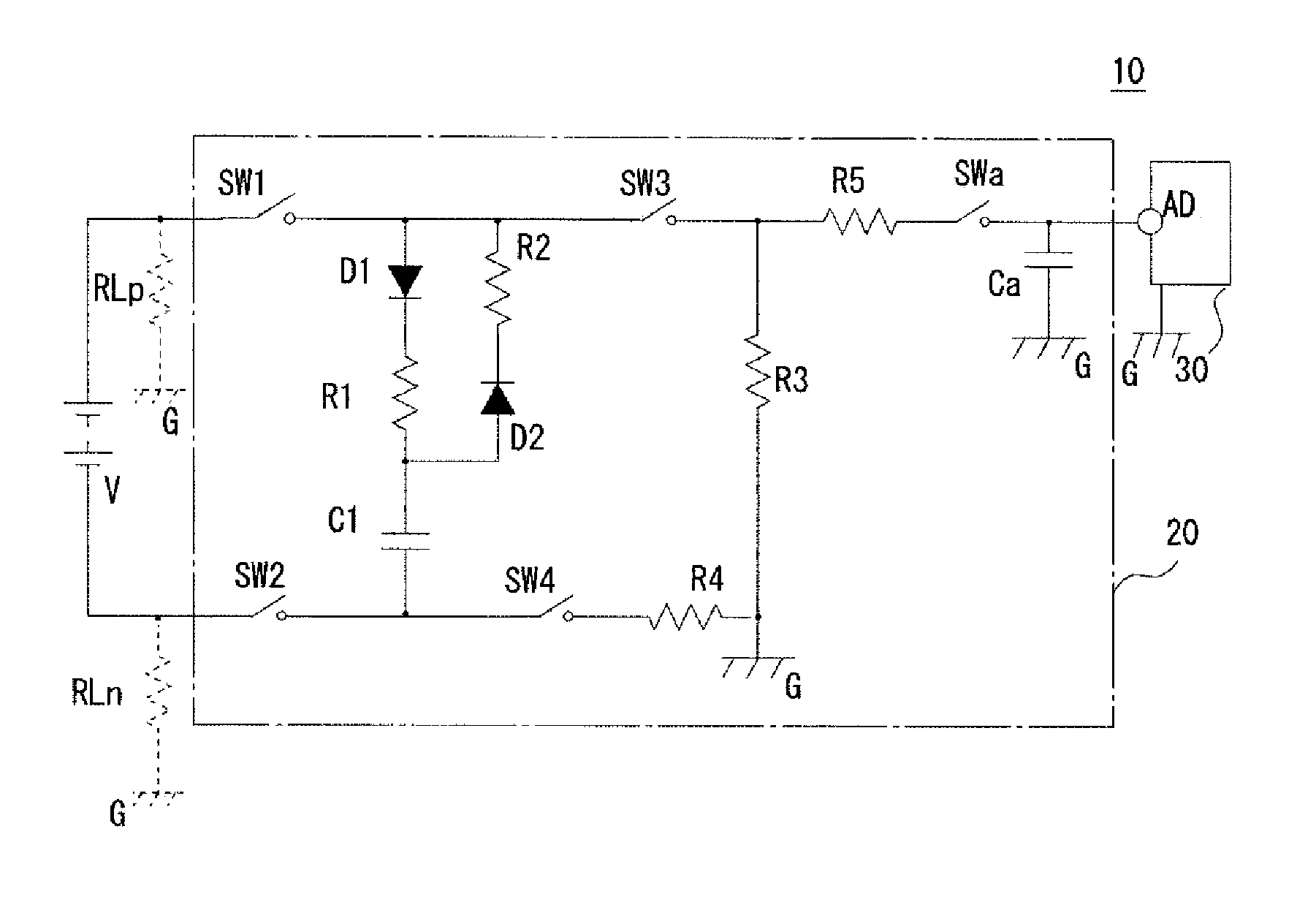
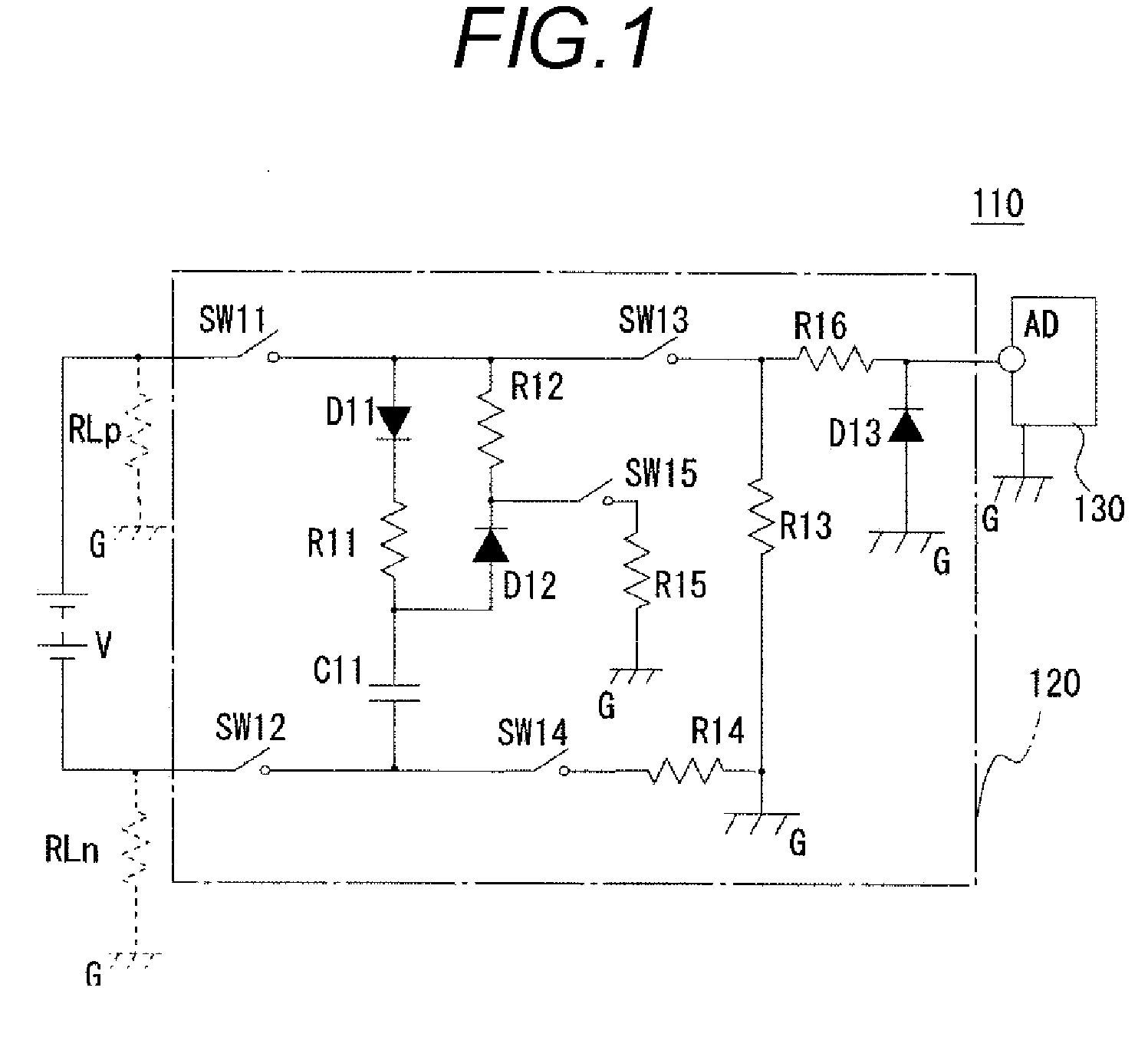
[0042]Embodiments for carrying out the invention will be explained with reference to the drawings hereinafter. In a first embodiment explained hereunder, the fifth switch SW15 and the fifth resistor R15 acting as the discharging circuit shown in the background art in FIG. 1 are omitted, and a low-voltage analog switch serving as an AD reading switch SWa is added into the input line to the input port AD. Also, an AD reading capacitor Ca that is also used as a filter is provided to constitute a sample and hold circuit. Also, in a second embodiment, as a variation of the first embodiment, a circuit from which diodes of the measuring system (the detection circuit) are omitted is proposed. Further, in a third embodiment, as a variation of the second embodiment, a circuit from which the AD reading switch SWa is omitted and the discharge of the electric charge during the reading of the AD reading capacitor Ca is corrected in the measuring means is proposed.
first embodiment
[0043]FIG. 3 is a circuit diagram showing a configuration of an insulation measuring circuit 10 according to a first embodiment of the present invention. As shown in FIG. 3, the insulation measuring circuit 10 includes a detecting circuit 20 and a decision control unit 30, and detects a leakage of electricity by checking an insulation state of the high-voltage power supply V connected to the detecting circuit 20. The insulation states of the positive-electrode side ground fault resistor PLp as an insulation resistance on the positive electrode side of the power supply V and the negative-electrode side ground fault resistor RLn as an insulation resistance on the negative electrode side are detected herein.
[0044]The decision control unit 30 has an input port AD, and is equipped with a voltage measuring function of AD-converting a voltage being input into the input port AD and then measuring the voltage, and a function of controlling the opening / closing of the first to fourth switches ...
second embodiment
[0066]In the present embodiment, as a variation of the first embodiment, such a circuit is proposed that a first resistor R21 as a charging resistor of the measuring system (high voltage circuit) is not shared in respective measuring modes. First, an insulation measuring circuit 210 shown in FIG. 5 will be explained as the premise technology hereunder. A decision control unit 230 has the similar configuration and functions to those of the decision control units 30, 130 in the first embodiment and the background art. The decision control unit 230 controls the opening / closing of first to fifth switches SW21 to SW25 and the AD reading switch SWa provided to a detecting circuit 220, and also makes a decision of the insulation degradation based on voltages (VC1p, VC1n, V0) that are input into the input port AD respectively.
[0067]In the detecting circuit 220, the first switch SW21, the first resistor R21, a capacitor C21, a second resistor R22, and the second switch SW22 are arranged in s...
PUM
 Abstract
Description
Claims
Application Information
 - R&D
- Intellectual Property
- Life Sciences
- Materials
- Tech Scout
- Unparalleled Data Quality
- Higher Quality Content
- 60% Fewer Hallucinations
Browse by: Latest US Patents, China's latest patents, Technical Efficacy Thesaurus, Application Domain, Technology Topic, Popular Technical Reports.
© 2025 PatSnap. All rights reserved.Legal|Privacy policy|Modern Slavery Act Transparency Statement|Sitemap|About US| Contact US: help@patsnap.com


