
Chuck for bit

a technology of chuck and bit, which is applied in the field of chuck for bit, can solve the problems of troublesome screw rotation through the operation of the tool, inefficient operation, and troublesome operation of the screw during the mounting or replacement of bits

Active Publication Date: 2013-02-05
HU BOBBY
View PDF70 Cites 26 Cited by
  • Summary
  • Abstract
  • Description
  • Claims
  • Application Information

AI Technical Summary

Benefits of technology

The present invention provides a chuck for bits that includes a body with first and second ends, a second end including an engaging groove for releasably receiving a bit, and a coupling section for rotational movement of the bit. A sleeve is mounted around the body and movable relative to the body between a coupling position and a releasing position, with an engaging section for joint rotation of the sleeve and the body when the sleeve is manually rotated. A flange is formed on the outer periphery of the body to provide friction when the sleeve is manually rotated. The chuck also includes a positioning member movable between an engaged position and a disengaged position for retaining the bit. A spring is mounted between the body and the sleeve to bias the sleeve to the coupling position. The coupling section of the body includes parallel, spaced chamfered faces, and the engaging section of the sleeve includes parallel, spaced flat faces engaged with the chamfered faces to allow joint rotation of the sleeve and the body. The technical effects of this invention are to provide an improved chuck for bits that allows for easy and secure coupling with a tool, as well as easy removal of the bit for replacement or repositioning.

Problems solved by technology

However, the chucks are usually utilized in an environment with oil such that the fingers of a user often slip and, thus, can not effectively move the sleeve to the releasing position, leading to problems during mounting or replacement of bits.
Furthermore, it is well known that when using a tool to tighten or loosen a fastener such as a screw, rotating the screw in a loose state through operation of the tool is troublesome and inefficient.

Method used


Image

  • Chuck for bit
  • Chuck for bit
  • Chuck for bit

Examples


Embodiment Construction

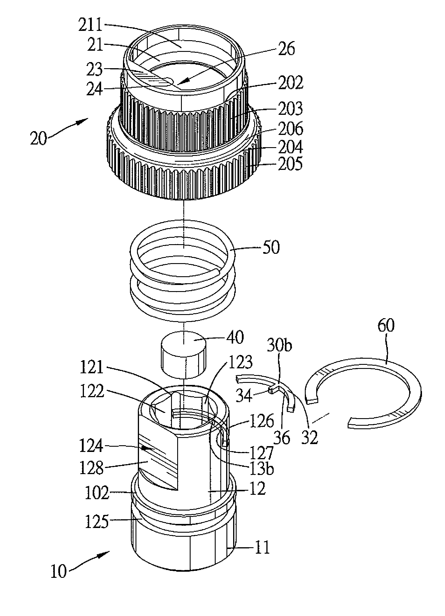
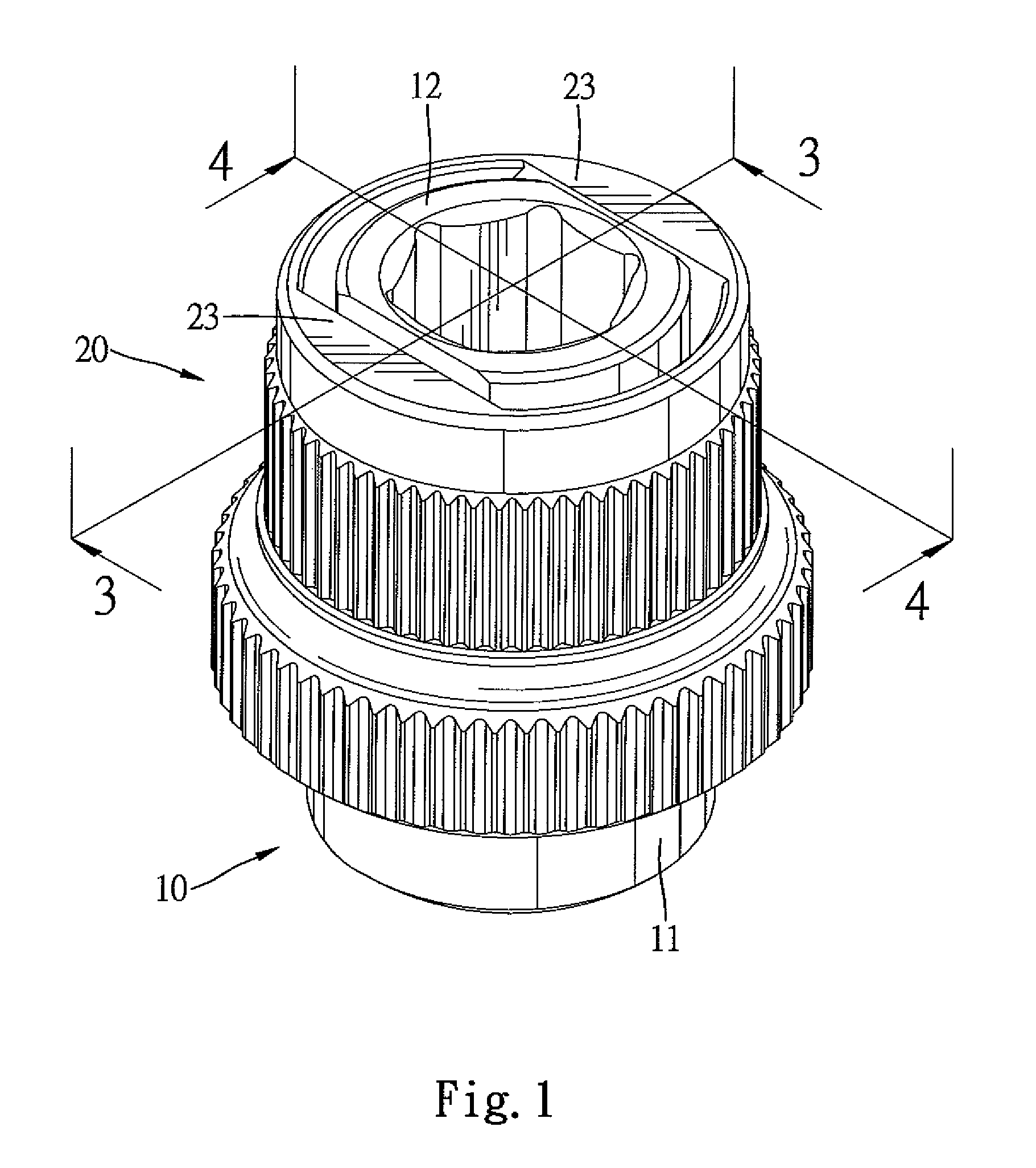
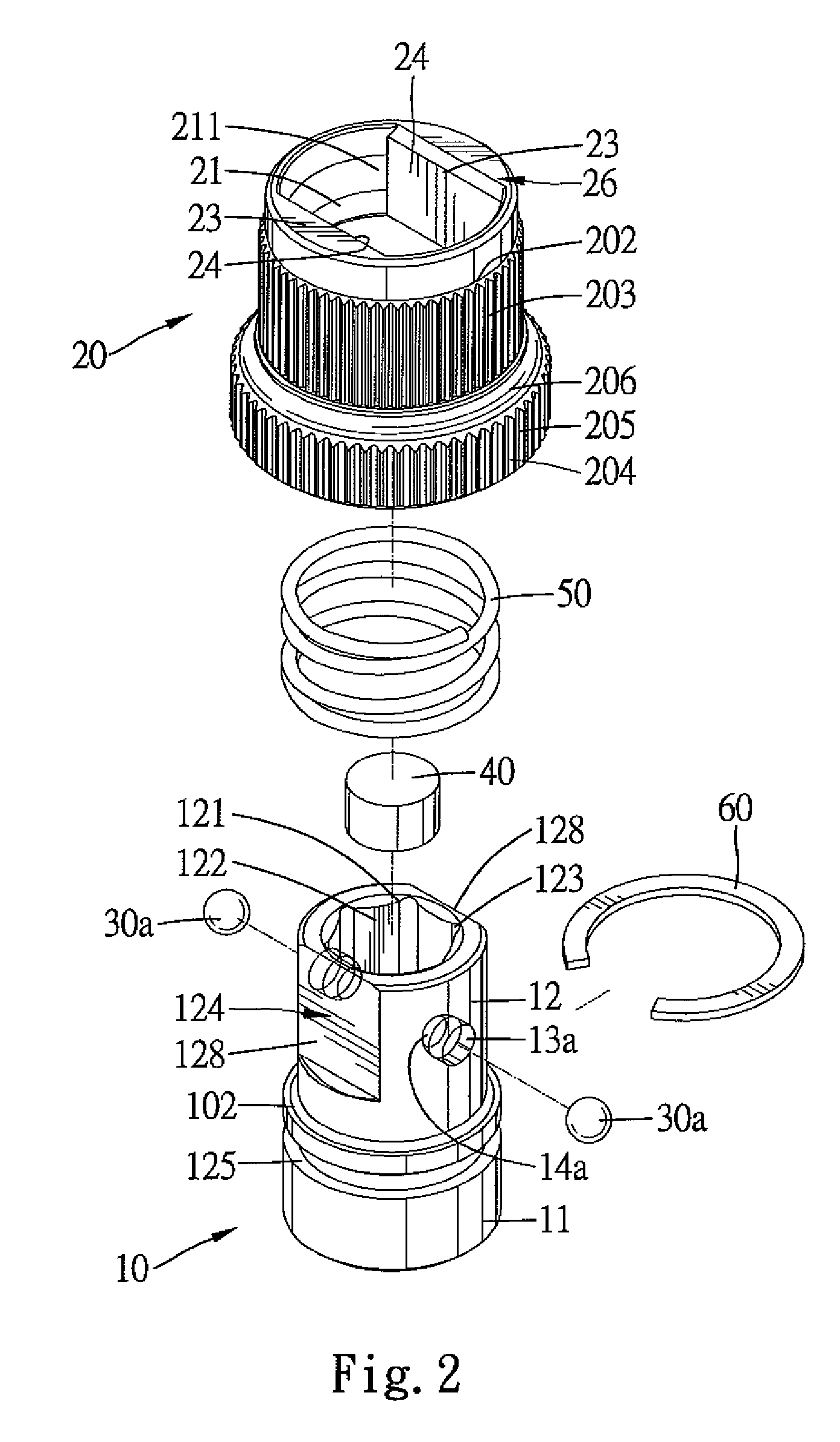
[0023]A chuck for a bit of an embodiment according to the preferred teachings of the present invention is shown in FIGS. 1-6 of the drawings. According to the preferred form shown, the chuck includes a body 10 having first and second ends 11 and 12 spaced along a longitudinal axis of body 10. Body 10 includes a longitudinal through-hole extending along the longitudinal axis and in the preferred form shown as having a coupling groove 111 and an engaging groove 121 respectively in first and second ends 11 and 12 of body 10 and an intermediate section 101 between coupling groove 111 and engaging groove 121. Coupling groove 111 releasably couples with a tool 90 in the preferred form shown as a socket wrench including a drive column 91 having a ball 92. According to the most preferred form shown, coupling groove 111 is square in cross section and includes four faces 112 each having a recess 113 for releasably engaging with ball 92 of drive column 91. It can be appreciated that drive colu...


PUM


Abstract

A chuck includes a body having an engaging groove for releasably receiving a bit. A sleeve is mounted around and movable relative to the body along a longitudinal axis of the body between a coupling position in which the bit is retained in the engaging groove and a releasing position allowing removal or insertion of the bit. The sleeve further includes an engaging section that slideably abuts a coupling section of the body. The engaging section is engaged with the coupling section to allow joint rotation of the body and the sleeve about the longitudinal axis. The sleeve further includes a flange with a frictional outer periphery to provide friction when the sleeve is manually rotated about the longitudinal axis by rotating the frictional outer periphery. Furthermore, the flange can be gripped by a user to move the sleeve to the releasing position.

Description

BACKGROUND OF THE INVENTION[0001]The present invention relates to a chuck for a bit and, more particularly, to a chuck for releasably receiving a bit such as a screwdriver bit.[0002]Various chucks have been developed to allow quick change of a bit such as a screwdriver bit. A typical quick-change chuck includes a body having a first end coupled to a wrench or a screwdriver handle and a second end with a groove into which a shank of a bit is removably mounted. A sleeve is mounted around the body and movable along a longitudinal axis of the body between a coupling position in which a ball is engaged with the shank of the bit and, thus, retains the shank in place and a releasing position in which the ball is disengaged from the shank to allow removal or mounting of the bit. A spring is provided to bias the sleeve to the coupling position. An example of such a chuck is disclosed in U.S. Pat. No. 4,629,375. However, the chucks are usually utilized in an environment with oil such that the...

Claims


Application Information

Patent Timeline
Patent Type & Authority Patents(United States)
IPC IPC(8): B23B31/107
CPCB25B15/001B25B23/0035Y10T279/17811Y10T279/17666Y10T279/17752Y10T279/23B25B23/12
Inventor HU, BOBBY
Owner HU BOBBY
Learn More