Bumper crossbeam as component of a bumper of a motor vehicle
a technology of bumper and crossbeam, which is applied in the directions of bumpers, vehicle safety arrangments, transportation and packaging, etc., can solve the problems of dimensional precision of the end product, and achieve the effects of fast fabrication, easy production, and fast adaptability
- Summary
- Abstract
- Description
- Claims
- Application Information
AI Technical Summary
Benefits of technology
Problems solved by technology
Method used
Image
Examples
first embodiment
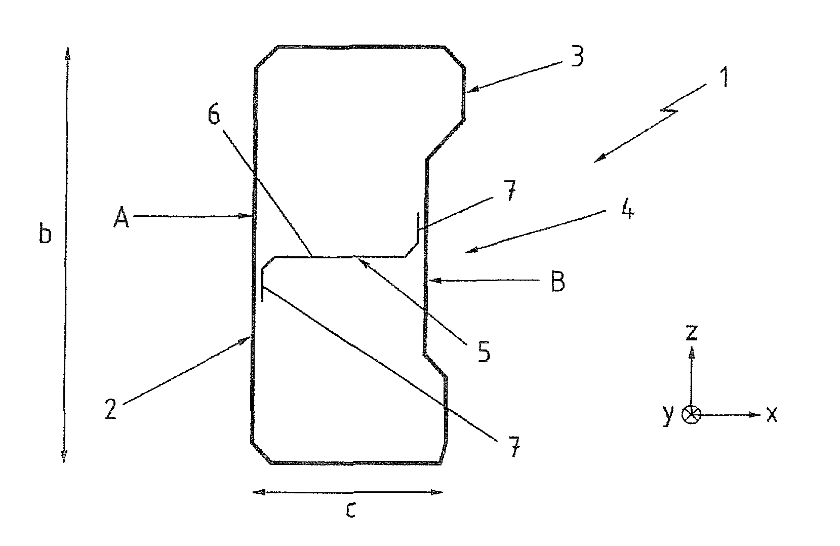
[0027]Turning now to the drawing, and in particular to FIG. 1, there is shown a schematic side view of a bumper crossbeam according to the invention, generally designated by reference numeral 1. The bumper crossbeam 1 has a substantially rectangular contour in cross section, defined by an outer section 2. The outer section 2 is formed by a hollow section 3. The outer cross sectional dimensions of the hollow section 3 indicate that a height b of the outer section 2, as measured in vertical direction z, is at least twice as high as its depth c measured perpendicular to the height b.
[0028]The component length extending in longitudinal axis of the bumper crossbeam 1 is not shown in greater detail, i.e. a yard ware produced by a continuous process is involved here.
[0029]The cross section of the outer section 2 is beveled in the corners of its contour and has a rear section zone A and a front section zone B on the opposite side. The contour in the section zone B of the outer section 2, co...
second embodiment
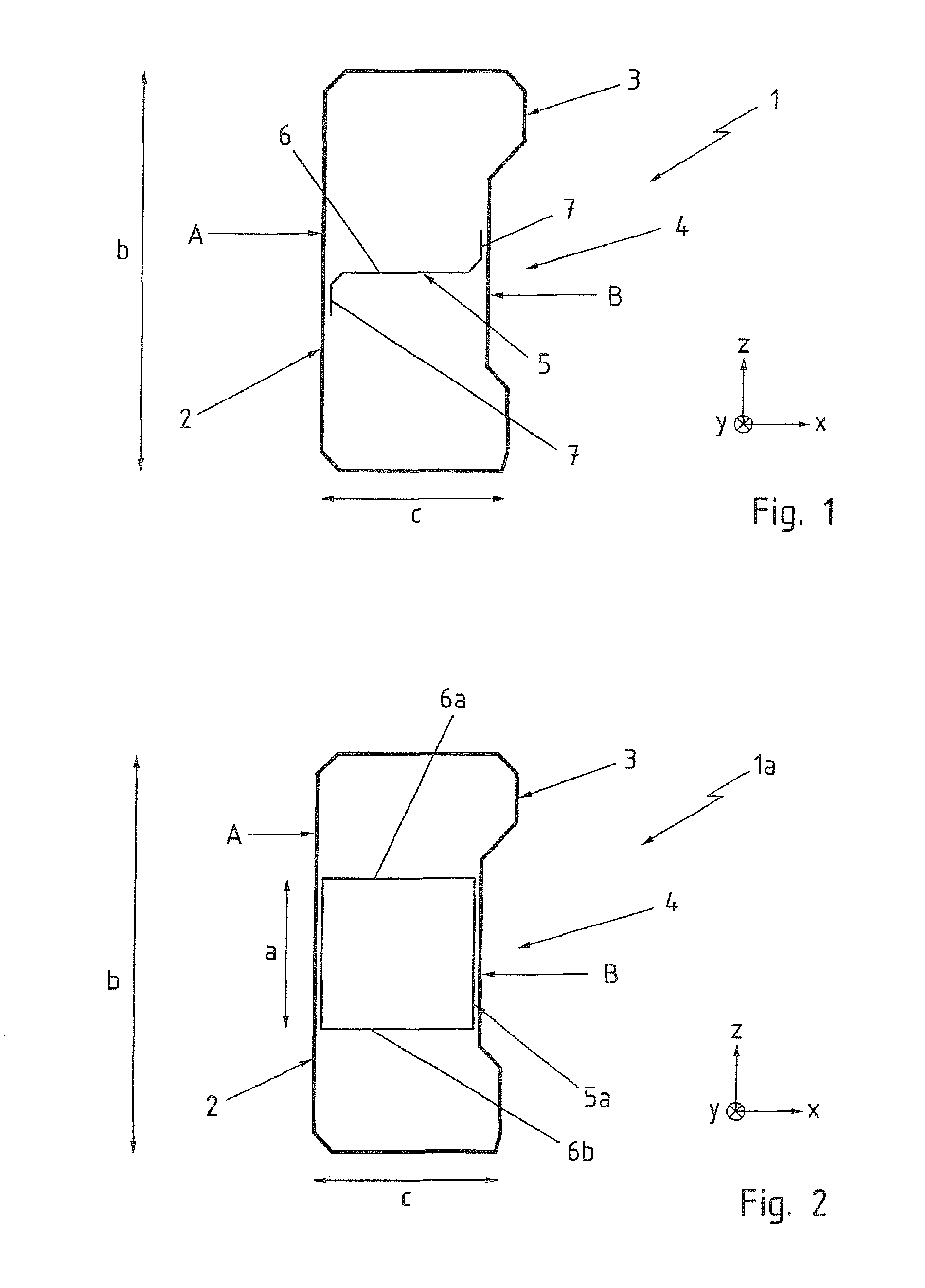
[0031]FIG. 2 shows a schematic side view of a bumper crossbeam according to the invention, generally designated by reference numeral 1a. In the following description, parts corresponding with those in FIG. 1 will be identified, where appropriate for the understanding of the invention, by corresponding reference numerals followed by an “a”. In this embodiment, the bumper crossbeam 1a includes the outer section 2 as hollow section, illustrated in FIG. 1. An inner section 5a is formed by a hollow section of rectangular cross section, with a wall 6a and a wall 6b respectively extending from the rear section zone A to the reinforcing embossments 4 in the section zone B. The inner section 5a has a height a measured in vertical direction z. The height a of the inner section 5a does not extend over the entire height b of the outer section 2 but is restricted only to the region of the front section zone B where the reinforcing embossment 4 is present.
third embodiment
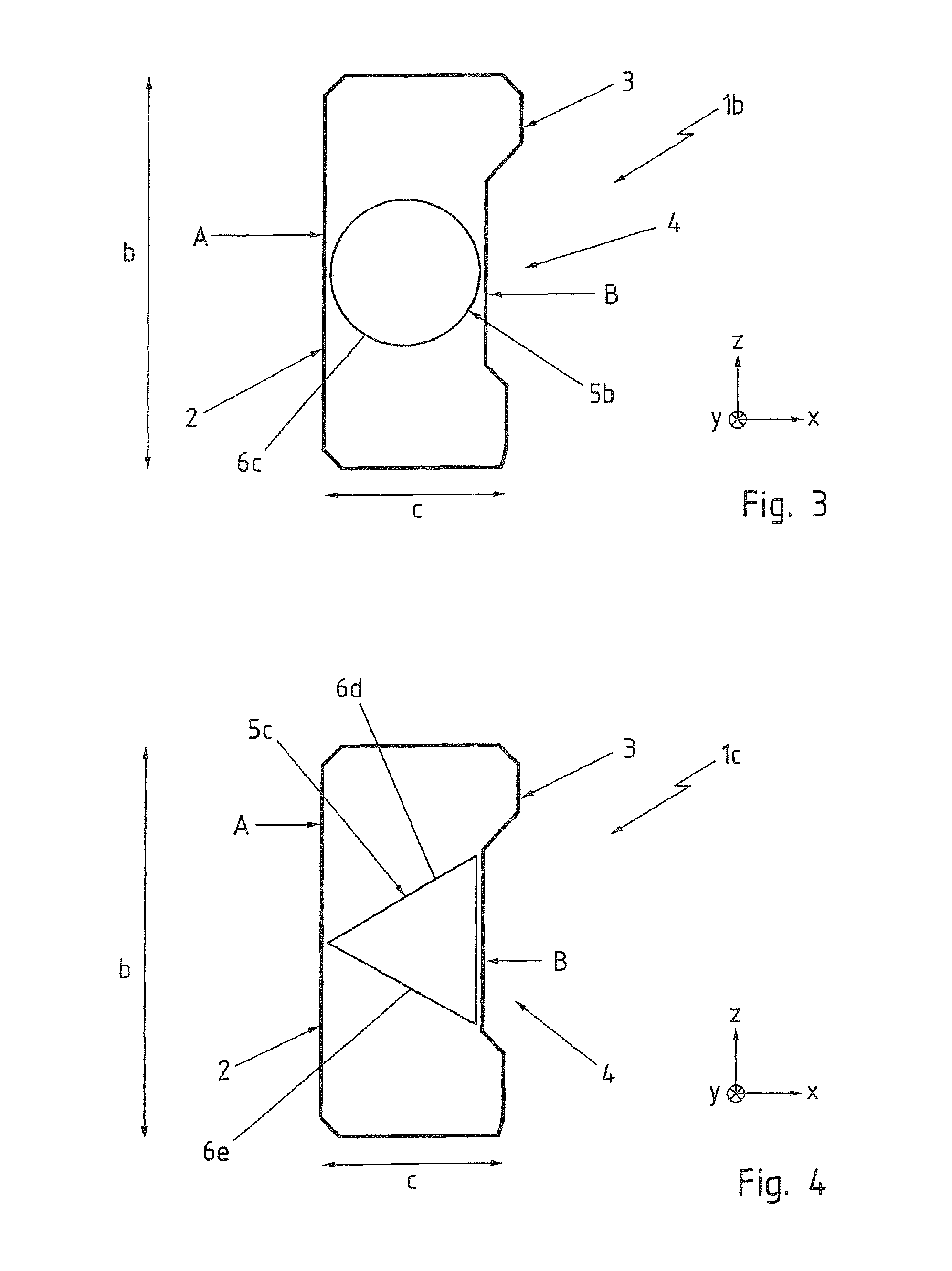
[0032]FIG. 3 shows a schematic side view of a bumper crossbeam according to the invention, generally designated by reference numeral 1b. In the following description, parts corresponding with those in FIG. 1 will be identified, where appropriate for the understanding of the invention, by corresponding reference numerals followed by a “b”. In this embodiment, the bumper crossbeam 1b also includes the outer section 2 as hollow section, illustrated in FIG. 1. Accommodated in the outer section 2 is an inner section 5b which is realized by a round hollow section in cross section. A rotation symmetric wall 6c of the inner section 5b also extends from the rear section zone A towards the reinforcing embossment 4 in the front section zone B.
PUM
 Abstract
Description
Claims
Application Information
 - R&D
- Intellectual Property
- Life Sciences
- Materials
- Tech Scout
- Unparalleled Data Quality
- Higher Quality Content
- 60% Fewer Hallucinations
Browse by: Latest US Patents, China's latest patents, Technical Efficacy Thesaurus, Application Domain, Technology Topic, Popular Technical Reports.
© 2025 PatSnap. All rights reserved.Legal|Privacy policy|Modern Slavery Act Transparency Statement|Sitemap|About US| Contact US: help@patsnap.com


