Ignition coil

a technology of ignition coil and ignition coil, which is applied in the direction of electrical equipment, transformer/inductance details, inductance, etc., can solve the problems of increased tooling cost, increased copper wire cost in the ignition coil, and increased copper wire cost in the process itself, so as to reduce the amount of copper wire, eliminate costly tooling, and reduce the amount of scrap produced

Active Publication Date: 2013-01-29
DELPHI TECH IP LTD
View PDF14 Cites 3 Cited by
  • Summary
  • Abstract
  • Description
  • Claims
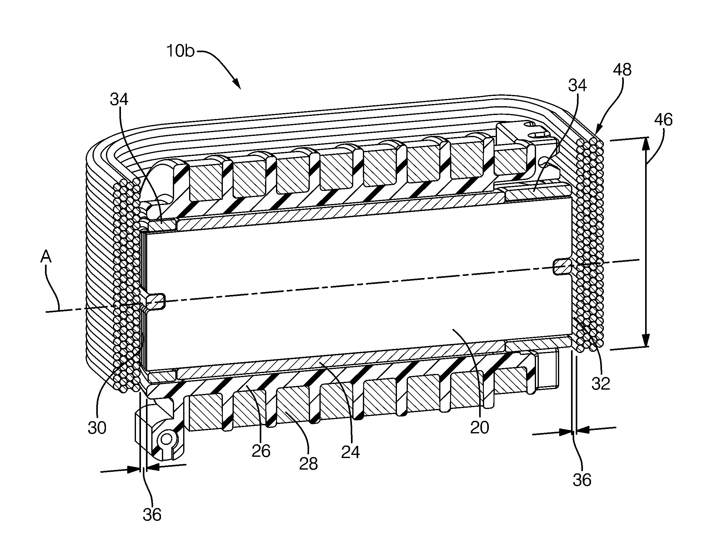
  • Application Information

AI Technical Summary

Benefits of technology

[0008]One advantage of the present invention is that it reduces the amount of copper wire used as compared to conventional ignition coils for comparable performance. Another advantage is that it reduces the amount of scrap produced during manufacture thereof. Still another advantage is that eliminates costly tooling to make the magnetic return path structure. Embodiments of the present invention achieve these advantages by providing a magnetic return path that eliminates scrap, can be made without costly tooling and which also permits the use of a circular-shaped magnetic core (i.e., where the primary winding can be wound directly around the core to reduce the MLT).
[0009]In one embodiment, an ignition apparatus includes a magnetically-permeable core, a primary winding, a secondary winding and a loop-shaped magnetically-permeable structure defining a high permeance magnetic return path. The core extends along an axis and has a pair of end surfaces on axially-opposite ends thereof. The core may preferably be circular to reduce the mean length per turn (MLT); however, other embodiments may be square or rectangular. The loop-shaped magnetic return path structure includes a plurality of layers of material (e.g., magnetically-permeable strip steel or ferritic wire in two preferred embodiments) stacked outwardly from its interior. The core is disposed in the interior of the loop-shaped structure so that the end surfaces of the core face opposing sides of the loop, and where at least one of the end surfaces is spaced apart from the loop to define an air gap.
[0010]In the strip steel embodiment, a length of strip steel is wound to form the plurality of layers that define the magnetic return path structure described above. The strip steel has width that corresponds to the width of the structure so no trimming, stamping or the like is involved and thus there is no scrap. In the wire embodiment, the ferritic wire may be black annealed iron wire, which is wound on a mandrel or the like into the desired loop-shape and then bonded. Again, the forming process does not produce any scrap.
[0011]In a still further embodiment, a combined core and magnetic return path structure is provided. In an initial production stage, a continuous loop-shaped structure is formed by winding ferritic wire either on a spool (in one variation) or on a mandrel (in another variation). Once formed, the initial structure is cut approximately in half to form two C-shaped portions. Each C-shaped portion has a respective central yoke (i.e., base) that extends into a pair of parallel legs. The C-shaped portions are re-assembled with respect to each other so that the legs form a pair of parallel branches. One branch acts as the core and around which is assembled the primary and secondary windings. The other branch defines the magnetic return path. Preferably, both branches include an air gap, for example, in the locations where the initial cuts occurred. Through the foregoing, an all-wire core and return path ignition apparatus is provided, which reduces use of copper, production of scrap as well as eliminating costly tooling.

Problems solved by technology

While there has always been an incentive to reduce the amount of copper wire in an ignition coil (and hence the cost attributable to copper), in recent times, the price of copper has increased over 400%, with the result that the cost of the copper wire in an ignition coil has become a significant portion of the total bill of materials (BOM).
Co-pending U.S. patent application Ser. No. 12 / 325,581 filed Dec. 1, 2008 entitled “IGNITION COIL WITH CYLINDRICAL CORE AND LAMINATED RETURN PATH” addresses some of the problems noted above; however, a C-shaped return path disclosed therein is a stamped part in which scrap is formed during manufacture, and which process itself involves increased cost tooling.

Method used


Image

  • Ignition coil
  • Ignition coil
  • Ignition coil

Examples


Embodiment Construction

[0024]Referring now to the drawings wherein like reference numerals are used to identify identical components in the various views, FIG. 1 is a simplified diagrammatic and block diagram view of an ignition system, with portions shown in cross-section, in which embodiments of an ignition apparatus 10 may be used. The ignition apparatus 10 may be controlled by a control unit 11 or the like, as known. The ignition apparatus 10 is configured for connection to a spark plug 12 that may be in threaded engagement with a spark plug opening 13 leading to a combustion cylinder of an internal combustion engine 14. The ignition apparatus 10 is configured to output a high-voltage (HV) output (e.g., on a high-voltage terminal 16) which is provided to the spark plug 12. Generally, overall spark timing (dwell control) and the like may be controlled by the control unit 11, which may be communicated as a control signal that is applied to a control terminal 18 of the ignition apparatus 10. In certain e...


PUM

PropertyMeasurementUnit
magnetically-permeableaaaaaaaaaa
magneticaaaaaaaaaa
electrical resistanceaaaaaaaaaa

Abstract

An ignition apparatus includes a core, primary and secondary windings and a loop-shaped magnetic return path structure. The structure includes layers of wound strip steel or wound ferritic wire stacked in an outward fashion. The core is placed in an interior of the loop forming at least one air gap between a core end surfaces and the structure. A combined core and magnetic return path structure includes a continuous loop formed by winding ferritic wire either on a spool or on a mandrel and is then bonded. The bonded winding is cut to form two C-shaped portions. Each C-shaped portion has a central yoke that extends into a pair of parallel legs. The C-shaped portions are re-assembled over primary and second windings so that the legs form a pair of parallel branches. One branch acts as the core and the other branch acts as the magnetic return path.

Description

CROSS REFERENCE TO RELATED APPLICATIONS[0001]This application claims the benefit of U.S. Provisional Patent Application Ser. No. 61 / 222,581 for an IGNITION COIL, filed on Jul. 2, 2009, which is hereby incorporated by reference in its entirety. This claim is made under 35 U.S.C. §119(e); 37 C.F.R. §1.78; and 65 Fed. Reg. 50093.INCORPORATION BY REFERENCE[0002]U.S. patent application Ser. No. 12 / 325,581 filed Dec. 1, 2008 entitled IGNITION COIL WITH CYLINDRICAL CORE AND LAMINATED RETURN PATH is hereby incorporated by reference in its entirety.TECHNICAL FIELD[0003]The present invention relates generally to an ignition apparatus or coil, and, more particularly, to an ignition apparatus that uses less copper wire and / or produces less scrap during manufacture than conventional arrangements.BACKGROUND OF THE INVENTION[0004]There has been much investigation in the development of an ignition apparatus for producing a spark for ignition of an internal combustion engine. As a result, the art ha...

Claims


Application Information

Patent Timeline
Patent Type & Authority Patents(United States)
IPC IPC(8): H01F38/12
CPCH01F3/06H01F3/14H01F38/12
Inventor SKINNER, ALBERT ANTHONYLEVERS, JR., HARRY OLIVERPAUL, MARK ALBERTHAMER, COLINHERRERA, HECTOR J.
Owner DELPHI TECH IP LTD
Why Eureka
Try Eureka