
Multi-modal transponder and method and apparatus to detect same

a transponder and multi-modal technology, applied in the field of detection of presence, or absence, and identification of objects tagged with transponders, can solve the problems of affecting the operation of the instrument, the cost of time-consuming, and the cost of maintenance, so as to and prevent damage and thus failure of the transponder

Active Publication Date: 2013-01-22
TYCO HEALTHCARE GRP LP
View PDF271 Cites 52 Cited by
  • Summary
  • Abstract
  • Description
  • Claims
  • Application Information

AI Technical Summary

Benefits of technology

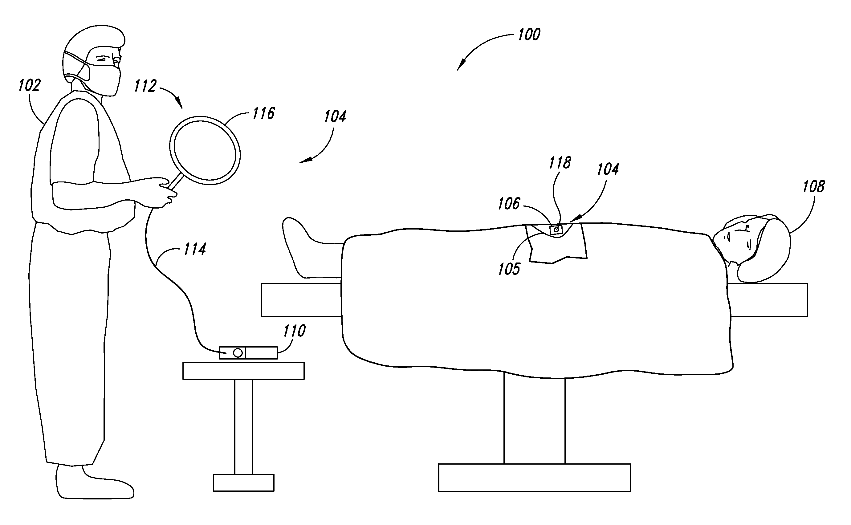
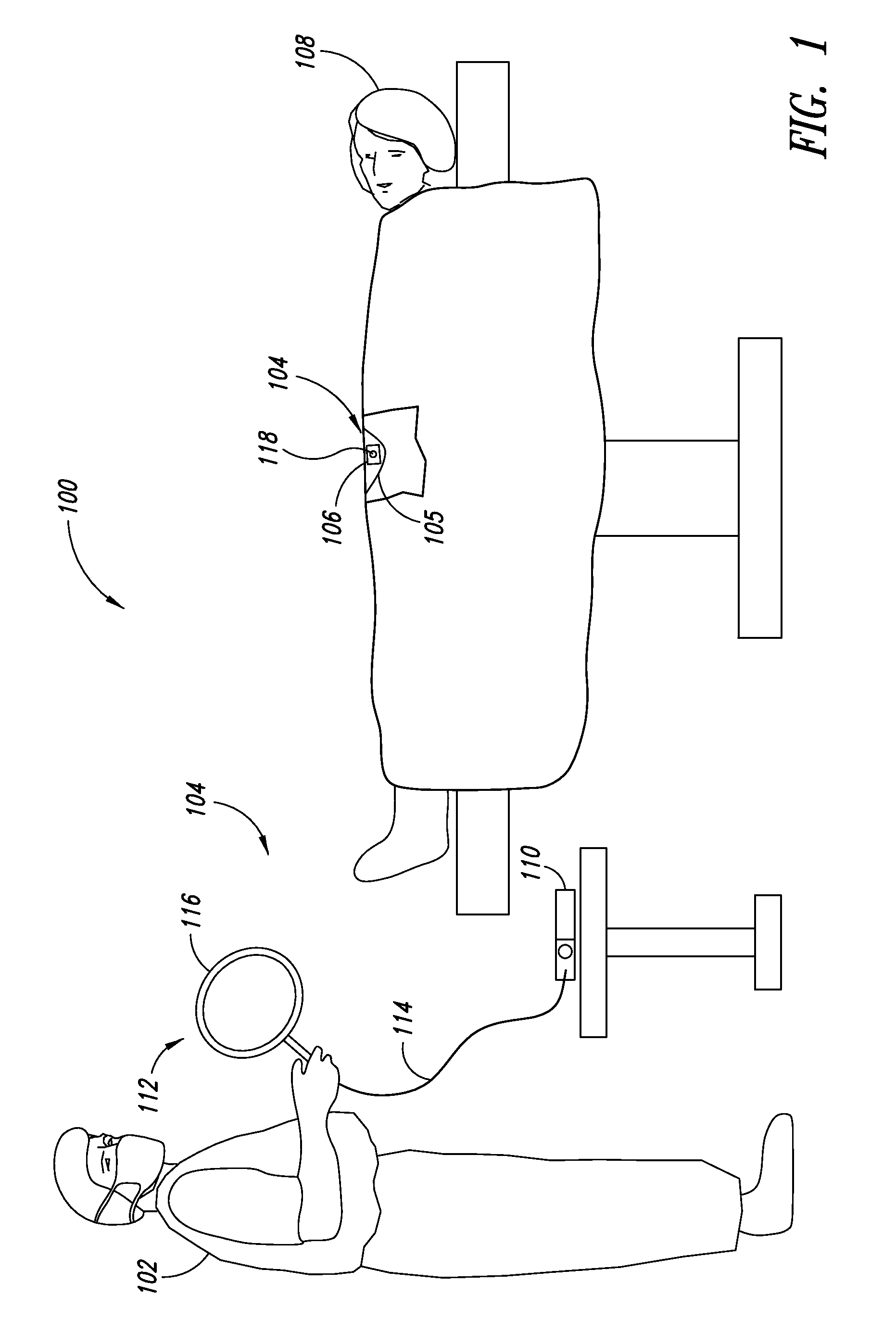
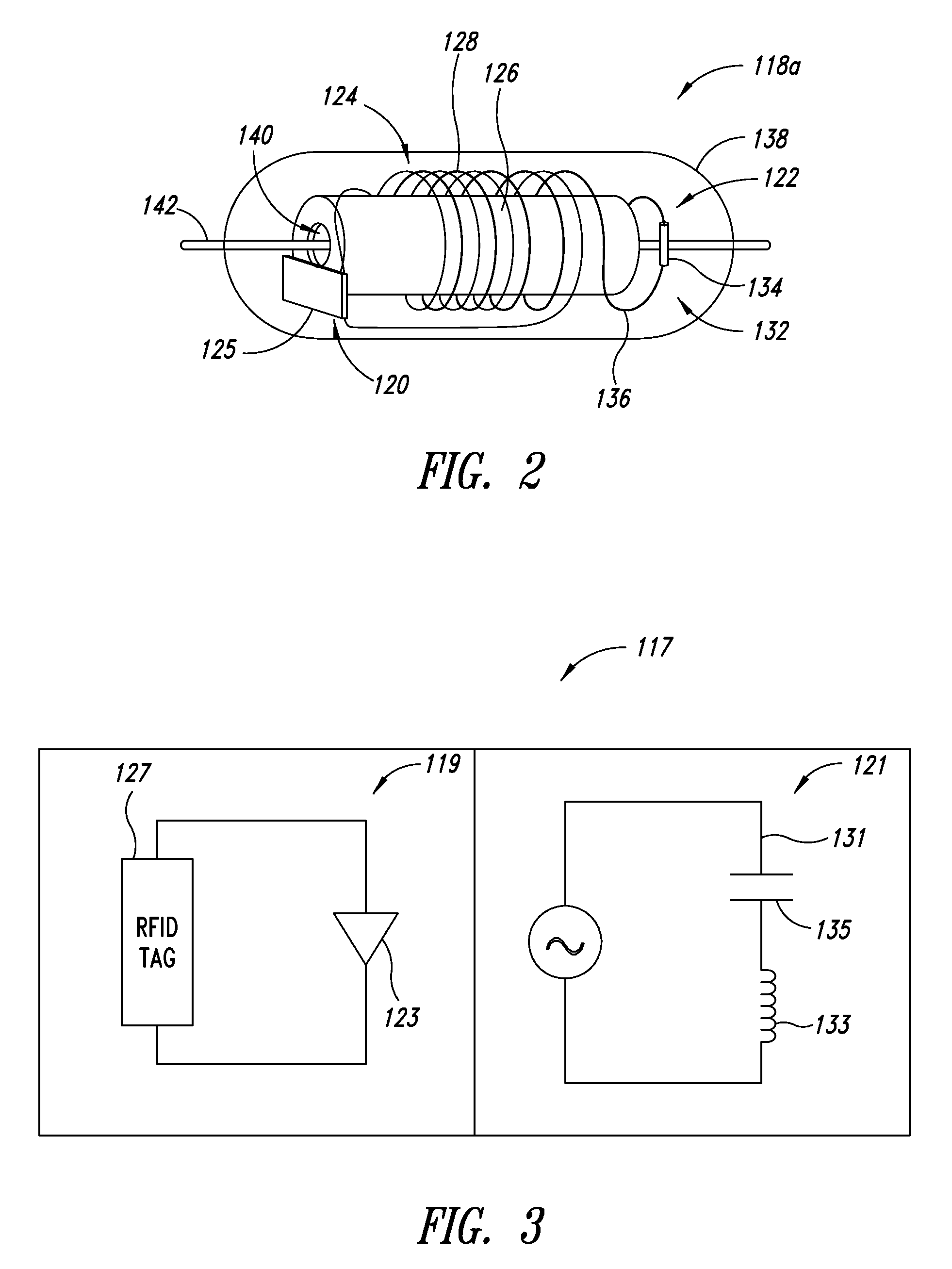
The patent describes a system for detecting and identifying objects using a combination of identification and presence / absence transponders. The system can be used in a medical or surgical context to detect and identify objects without the need for costly and time-consuming manual tracking or computerized systems. The system includes an identification transponder with a unique identifier and a presence / absence transponder that sends a signal when the object is present or absent. The two transponders are physically coupled to each other, allowing them to be selectively attached to the object. The system can be used to determine the object's identity, life cycle, and maintenance cycle. It can also be used to scan the objects present in a surgery and determine if they are still present after being disinfected. Overall, the system provides a more efficient and cost-effective way to detect and identify objects in various settings.

Problems solved by technology

For example, in the medical or surgical context, tools such as those listed above, can have a limited shelf life after being disinfected and before being used or reused.
Furthermore, some tools have a total life cycle after which they need to be replaced or go through maintenance before being reused.
Conventional manual tracking of an object's life cycle, maintenance cycle, shelf life or any other parameter, even when assisted by computers, can be costly and time-consuming.

Method used


Image

  • Multi-modal transponder and method and apparatus to detect same
  • Multi-modal transponder and method and apparatus to detect same
  • Multi-modal transponder and method and apparatus to detect same

Examples


Embodiment Construction

[0041]In the following description, certain specific details are set forth in order to provide a thorough understanding of various disclosed embodiments. However, one skilled in the relevant art will recognize that embodiments may be practiced without one or more of these specific details, or with other methods, components, materials, etc. In other instances, well-known structures associated with transmitters, receivers, or transceivers have not been shown or described in detail to avoid unnecessarily obscuring descriptions of the embodiments.

[0042]Unless the context requires otherwise, throughout the specification and claims which follow, the word “comprise” and variations thereof, such as, “comprises” and “comprising” are to be construed in an open, inclusive sense, that is as “including, but not limited to.”

[0043]Reference throughout this specification to “one embodiment” or “an embodiment” means that a particular feature, structure or characteristic described in connection with ...


PUM


Abstract

An integral detection and identification system for detecting and identifying an object includes an identification transponder and a presence / absence transponder. The identification transponder includes a first inductive winding wound about a core and electrically coupled to an integrated circuit to transmit an identification signal in response to receipt of an interrogation signal in a first frequency range. The identification signal encodes an identifier stored by the integrated circuit. The presence / absence transponder includes a resonant inductive / capacitive tank circuit having at least a second inductive winding wound about a core and electrically coupled to a capacitor to transmit a presence / absence signal in response to an interrogation signal in a second frequency range. The presence / absence response signal lacks unique identifying information and is physically coupled to the identification transponder to form an integral detection and identification transponder that can selectively be attached to the object.

Description

CROSS-REFERENCE(S) TO RELATED APPLICATION(S)[0001]This application claims the benefit under 35 U.S.C. §119(e) of U.S. Provisional Patent Application Ser. No. 61 / 056,229, filed May 27, 2008 and U.S. Provisional Patent Application Ser. No. 61 / 102,749, filed Oct. 3, 2008.BACKGROUND[0002]1. Field[0003]The present disclosure generally relates to detection of presence, or absence, and identification of objects tagged with transponders, which may, for example, allow detection and identification of surgical objects (e.g., sponges, instruments, etc.) during or after surgery, or for inventorying of objects, for instance surgical objects.[0004]2. Description of the Related Art[0005]It is often useful or important to be able to determine the presence or absence of an object.[0006]For example, it is important to determine whether objects associated with surgery are present in a patient's body before completion of the surgery. Such objects may take a variety of forms. For example, the objects may...

Claims


Application Information

Patent Timeline
Patent Type & Authority Patents(United States)
IPC IPC(8): G08B21/00
CPCA61B5/06A61B19/44G06K7/0008G06K7/10128G06K19/07749A61B2019/448G06K2017/009A61B90/90A61B90/98
Inventor BLAIR, WILLIAM A.
Owner TYCO HEALTHCARE GRP LP
Learn More