
Self-heating integrated circuit

a technology of integrated circuits and integrated circuits, applied in the direction of individual semiconductor device testing, semiconductor/solid-state device details, instruments, etc., can solve the problems of damage to the test probes used for testing the integrated circuit, the difficulty of accurately controlling the temperature of the integrated circuit during testing,

Active Publication Date: 2013-01-22
WESTERN DIGITAL TECH INC
View PDF43 Cites 117 Cited by
  • Summary
  • Abstract
  • Description
  • Claims
  • Application Information

AI Technical Summary

Benefits of technology

The present invention relates to a method and apparatus for testing integrated circuits at different temperatures to ensure proper operation across a range of temperatures. The integrated circuit is placed inside a thermal chamber and heated up to a target temperature using a heating apparatus. The integrated circuit is tested at different temperatures by heating the chamber and using a temperature feedback loop to control the temperature. The invention provides a more accurate and efficient way to test integrated circuits, as it allows for precise control of temperature and reduces damage to the test probes. The technical effects of the invention include improved accuracy and efficiency in testing integrated circuits and reduced damage to test probes.

Problems solved by technology

In many cases, the integrated circuit is a few degrees off the chamber temperature, which makes it difficult to accurately control temperature of the integrated circuit during testing.
Also, the elevated temperatures in the thermal chamber may damage the test probes used for testing the integrated circuit.

Method used


Image

  • Self-heating integrated circuit
  • Self-heating integrated circuit
  • Self-heating integrated circuit

Examples


Embodiment Construction

[0013]In the following detailed description, numerous specific details are set forth to provide a full understanding of the present invention. It will be apparent, however, to one ordinarily skilled in the art that the present invention may be practiced without some of these specific details. In other instances, well-known structures and techniques have not been shown in detail to avoid unnecessarily obscuring the present invention.

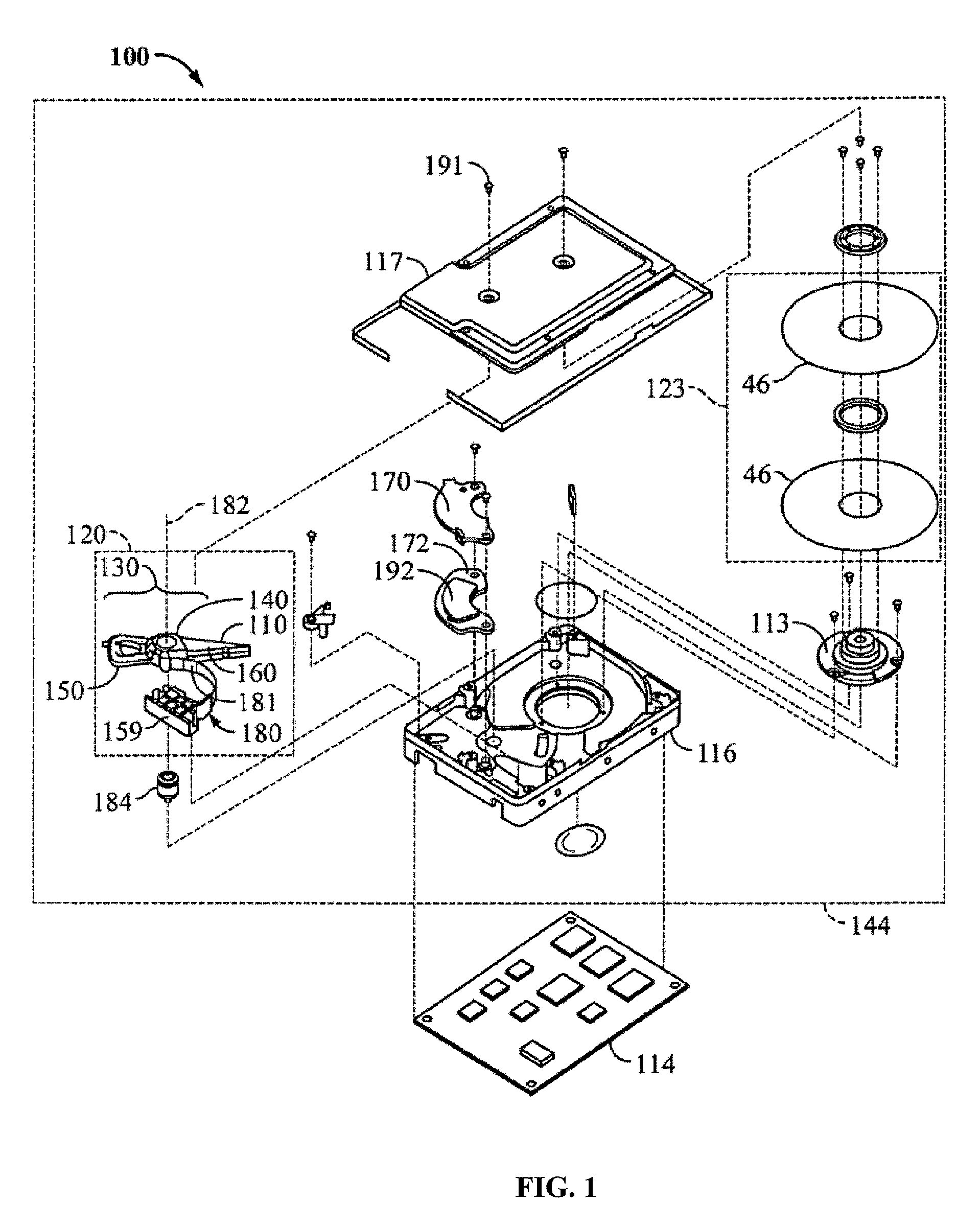
[0014]FIG. 1 is a perspective view illustrating the principal mechanical components of an example of a disk drive 100 that may be utilized with embodiments of the invention. The disk drive 100 comprises a head disk assembly (HDA) 144 and a printed circuit board assembly (PCBA) 114. The HDA 144 includes a disk drive enclosure comprising a base 116 and a cover 117 attached to the base 116 that collectively house a disk stack 123 that includes one or a plurality of magnetic disks (e.g. disks 46), a spindle motor 113 attached to the base 116 for rotating the ...


PUM


Abstract

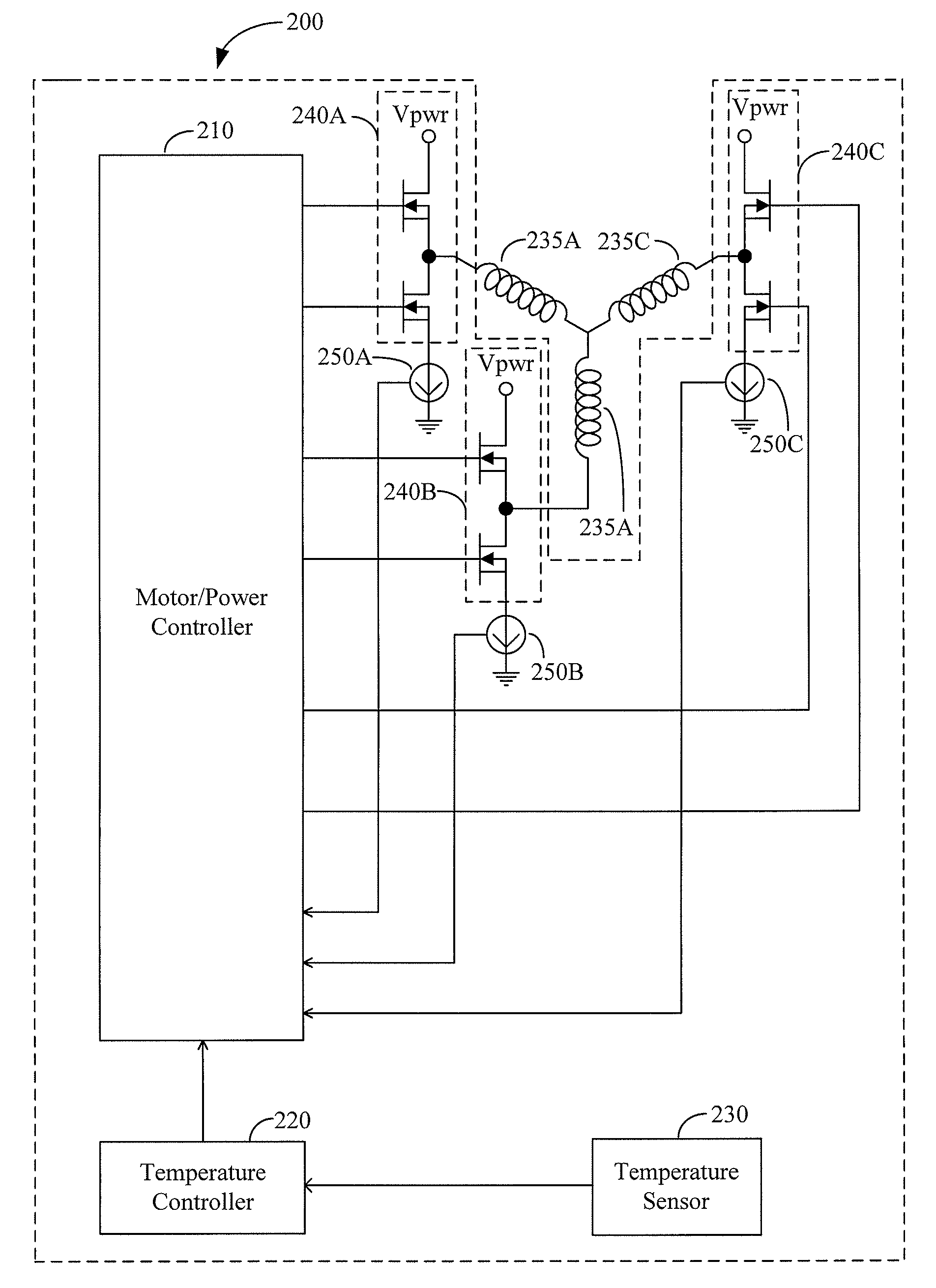
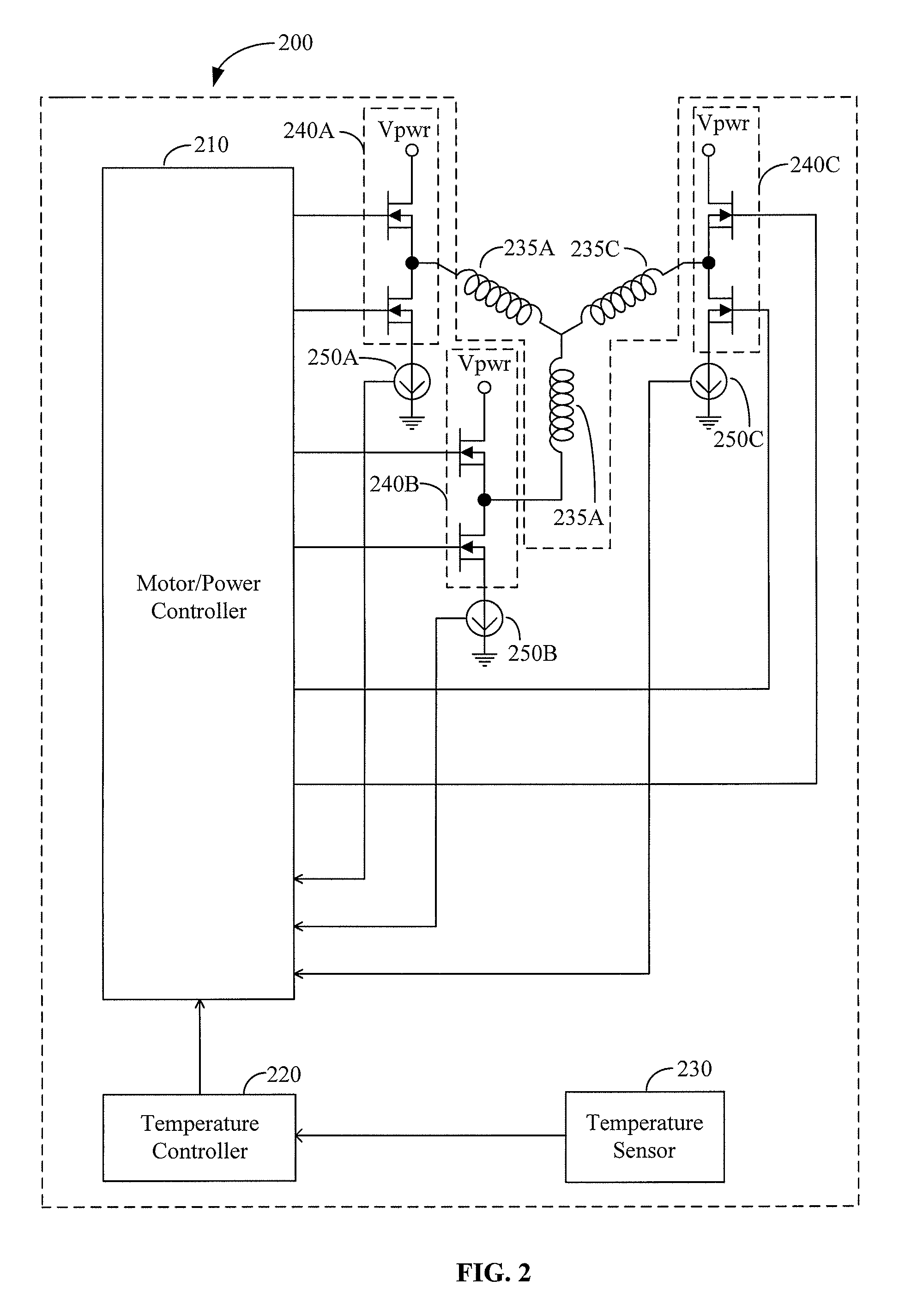
Self-heating integrated circuits are provided. In one embodiment, a self-heating integrated circuit comprises a drive circuit configured to drive a device and a controller configured to selectively operate the drive circuit in a first mode or a second mode. In the first mode, the controller is configured to operate the drive circuit to drive the device and, in the second mode, the controller is configured to operate the drive circuit to heat the integrated circuit to a target temperature.

Description

BACKGROUND OF THE INVENTION[0001]When a new integrated circuit is received from a supplier, the integrated circuit may be tested over a range of temperatures to verify that the integrated circuit operates properly across the range of temperatures. The range of temperatures during testing may be from room ambient temperature to elevated temperatures (e.g., 125° C.).[0002]The integrated circuit is tested at different temperatures by heating the integrated circuit. In one approach, the integrated circuit and test probes for testing the integrated circuit are placed inside a thermal chamber and the thermal chamber is heated to a target temperature. The integrated circuit is allowed to soak inside the thermal chamber for about 30 minutes to ensure that the integrated circuit reaches the target temperature. In many cases, the integrated circuit is a few degrees off the chamber temperature, which makes it difficult to accurately control temperature of the integrated circuit during testing....

Claims


Application Information

Patent Timeline
IPC IPC(8): G01R31/00
CPCG11B19/048G11B19/28G06F11/24H01L2924/0002H01L2924/00G01R31/26H01L23/345
Inventor FERRIS, TIMOTHY A.AGNESS, JOHN R.
Owner WESTERN DIGITAL TECH INC
Learn More