
Corner protector

a guard device and corner guard technology, applied in the direction of furniture parts, machine supports, other domestic objects, etc., can solve the problems of deficient operation of the corner guard of the prior art, and inability to protect the edge of the tabl

Active Publication Date: 2013-01-22
DREW THOMAS J
View PDF35 Cites 3 Cited by
  • Summary
  • Abstract
  • Description
  • Claims
  • Application Information

AI Technical Summary

Benefits of technology

The solution provides comprehensive protection by preventing bulging and allowing for customizable coverage of various hazardous areas, ensuring maximum safety and comfort for children by interlocking bumpers to prevent exposure to sharp edges and corners.

Problems solved by technology

The corner guards of the prior art are deficient in their operation.
The corner guards have a distinct and asymmetric shape and cannot be used to provide protection for other dangerous conditions such as at an edge of a table adjacent to the corner, over electrical appliances or over a glass windowpane.
Although, the corner guard is disposed over the corner, the edge of the table is not protected whatsoever and poses a danger, especially to an infant or toddler.
Further, the corner guards of the prior art have a number of corners that may potentially bulge outward, especially when placed adjacent to another second corner guard.
Moreover, upon bulging, the prior art corner guards provide no relief when placed over an edge of a table.
Moreover, the arrangement of tie strings and the elastic hem to attach to the corner of the table although providing cushioning by the padding still do not provide an adequate amount of protection, especially in the instance of a fall where relatively great force occurs relative to a mere bump.
Further, the corner guard still does not provide adequate protection and the infant may become injured if the corner guard merely has the padding therein.
This may result in the padded corner still being able to bruise and / or provide discomfort to the infant in a relatively higher force collision.

Method used


Image

  • Corner protector
  • Corner protector
  • Corner protector

Examples


Embodiment Construction

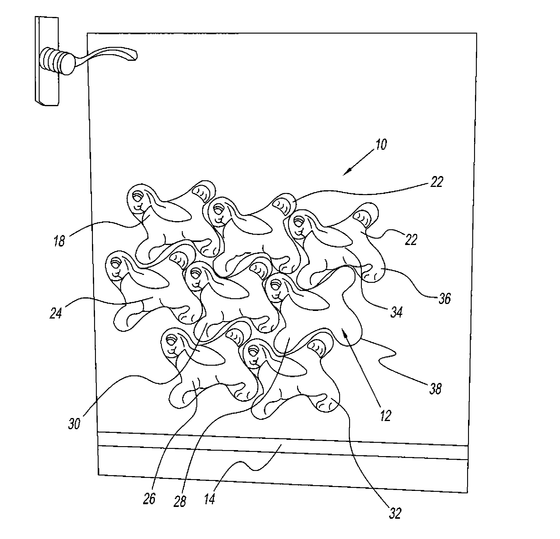
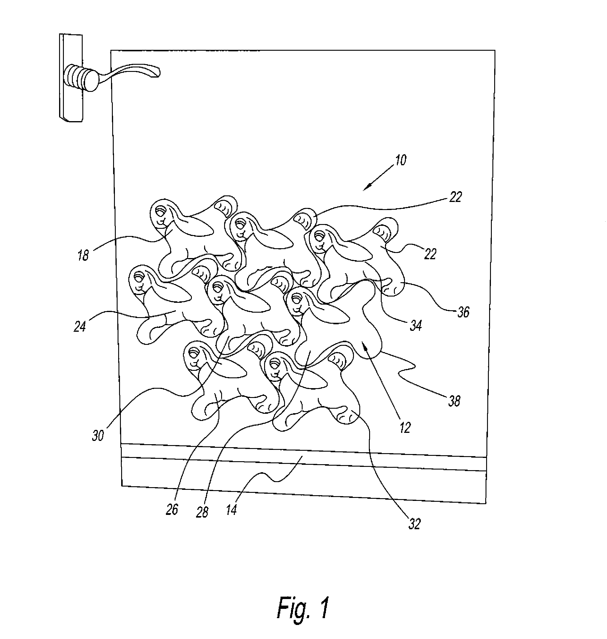
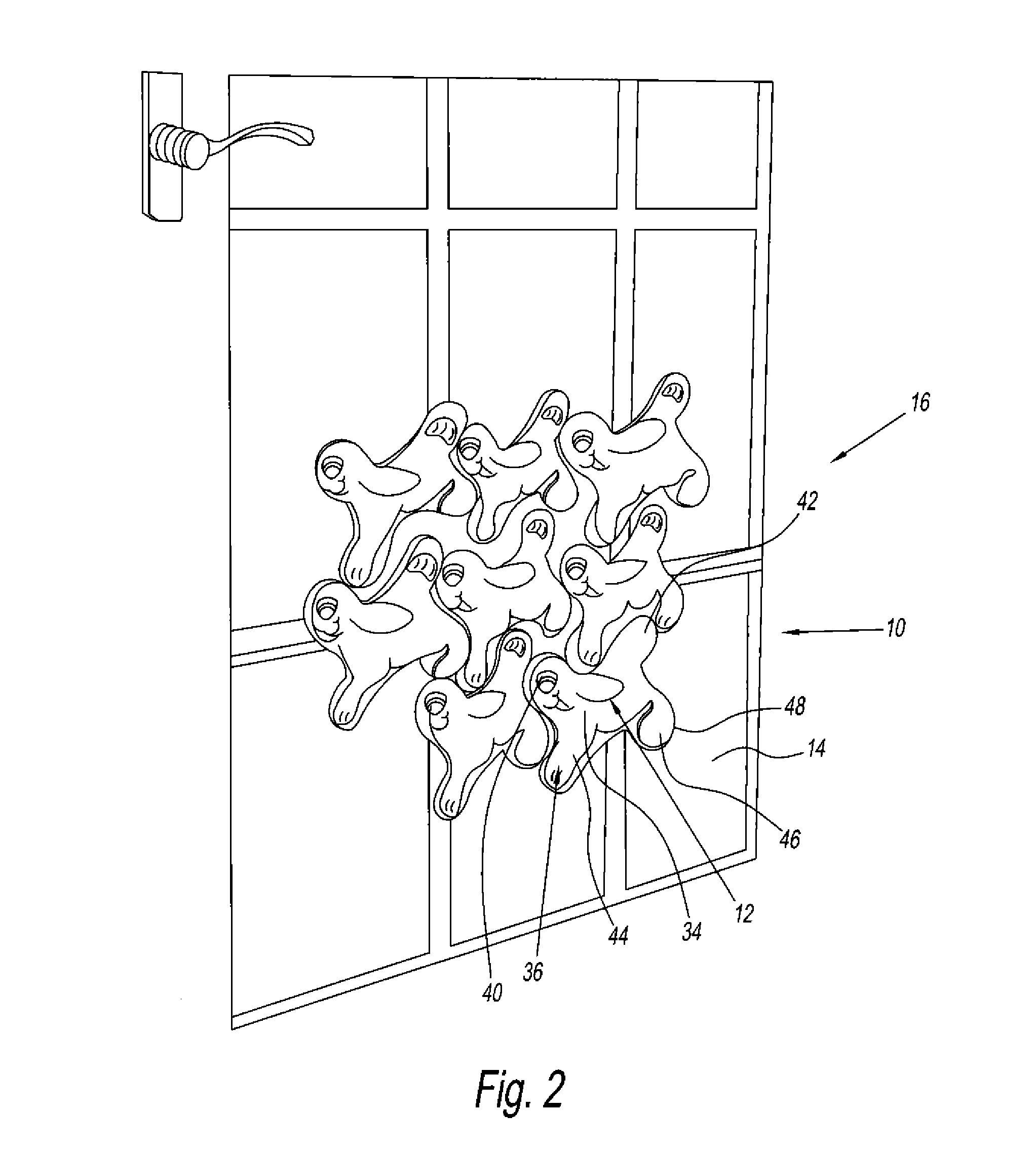
[0036]Referring to FIG. 1, there is provided a bumper assembly of the present invention generally represented by reference numeral 10. The bumper assembly 10 preferably is a configuration of a number of bumpers 12. Preferably, each of the bumpers 12 can be connected to one another or contiguously at a number of different locations to cover a potentially hazardous location of a household, such as a corner of a furniture item, an edge of a furniture item, an electrical appliance or a window. Preferably, a user can selectively create the bumper assembly 10 and selectively increase or decrease an amount of protection by connected the number of bumpers 12 in a modular type fashion.

[0037]Each of the number of bumpers 12 preferably has a substantially symmetrical and / or complimentary shape. In one embodiment of the present invention, the number of bumpers 12 each may have a shape. The shape may be a trapezoid, a square, a rectangle, a parallelogram, a symmetrical and / or complimentary shape...


PUM


Abstract

A human impact protection apparatus includes a body portion formed of a first resilient material and a plurality of members protruding radially outward from the body portion. The plurality of members are formed of a second resilient material which is the same as or different from the first resilient material. The plurality of members are adjacent one another and are separated by one or more spaces. An adhesive material or a mechanical fastener is disposed about one or both of the body portion and the plurality of members, whereby the apparatus may be affixed to a surface.

Description

CROSS REFERENCE TO RELATED PATENT APPLICATIONS[0001]This application is a continuation-in-part of co-pending U.S. patent Ser. No. 11 / 091,988 filed on Mar. 29, 2005 that claims priority to U.S. Provisional Patent Application Ser. No. 60 / 557,280 filed on Mar. 29, 2004 the contents of each of which are incorporated by reference herein in their entirety.BACKGROUND OF THE INVENTION[0002]1. Field of the Invention[0003]The present invention relates to a device that protects young children. More particularly, the present invention relates to a guard device that protects infants from a corner of furniture, glass, or other dangerous conditions in a household setting.[0004]2. Description of the Related Art[0005]Corner guards for tables are known in the art. One such corner guard is disclosed in U.S. Pat. No. 4,817,902 to Mason. Mason discloses a two-part corner protector. The corner guard provides for a padded covering of a corner of a structure. The two-part corner protector has a resilient i...

Claims


Application Information

Patent Timeline
Patent Type & Authority Patents(United States)
IPC IPC(8): A47B95/00
CPCA47B95/043Y10T428/24198
Inventor DREW, THOMAS J.
Owner DREW THOMAS J
Learn More