Rolled medium accommodation device and liquid ejection device

a technology of a housing device and a which is applied in the direction of thin material processing, printing, other printing devices, etc., can solve the problems of affecting the ease of operation, affecting the total weight of pushing the roll paper housing unit with greater force. , to achieve the effect of convenient replacemen

Active Publication Date: 2013-01-08
SEIKO EPSON CORP
View PDF4 Cites 2 Cited by
  • Summary
  • Abstract
  • Description
  • Claims
  • Application Information

AI Technical Summary

Benefits of technology

[0010]At this time, when a small-diameter roll paper with little paper remaining is accommodated or when no roll paper is being accommodated, the total weight of the roll paper accommodation unit is lighter, and the rotational torque in the falling direction created by the total weight of the roll paper accommodation unit is therefore small. As a result, a relatively large rotational torque in the rising direction of the roll paper accommodation unit is created by the set urging force of the gas spring. Therefore, when the roll paper accommodation unit is lowered and the liquid ejection device is returned to the usage state, the operating force needed in order to push the roll paper accommodation unit down in the direction of gravity is greater, the operator must therefore push the roll paper accommodation unit down with greater force, and the ease of operability is adversely affected.
[0030]According to this configuration, in the rolled medium accommodation device, the rolled medium accommodation unit can be held in the high position so as to not swing (fall) in the direction of gravity, even when an unused rolled medium or another maximum-weight rolled medium is accommodated in the rolled medium accommodation unit. Consequently, it is possible to achieve a liquid ejection device in which, for example, a rolled medium accommodated in the liquid ejection device can be easily replaced.

Problems solved by technology

However, since the roll paper accommodated in the roll paper accommodation unit decreases in weight as the paper is consumed, there is a difference in the total weight of the roll paper accommodation unit between a state in which a new, unused large-diameter roll paper is accommodated and a state in which a small-diameter roll paper with little paper remaining is accommodated.
Therefore, when the roll paper accommodation unit is lowered and the liquid ejection device is returned to the usage state, the operating force needed in order to push the roll paper accommodation unit down in the direction of gravity is greater, the operator must therefore push the roll paper accommodation unit down with greater force, and the ease of operability is adversely affected.
However, when this is done, the rotational torque in the rising direction caused by the urging force of the gas spring decreases and therefore can no longer oppose the rotational torque in the falling direction when new, unused roll paper is accommodated in the roll paper accommodation unit, i.e., when the roll paper accommodation unit is at its heaviest weight.
As a result, the roll paper accommodation unit falls due to its own weight.

Method used


Image

  • Rolled medium accommodation device and liquid ejection device
  • Rolled medium accommodation device and liquid ejection device
  • Rolled medium accommodation device and liquid ejection device

Examples


first embodiment

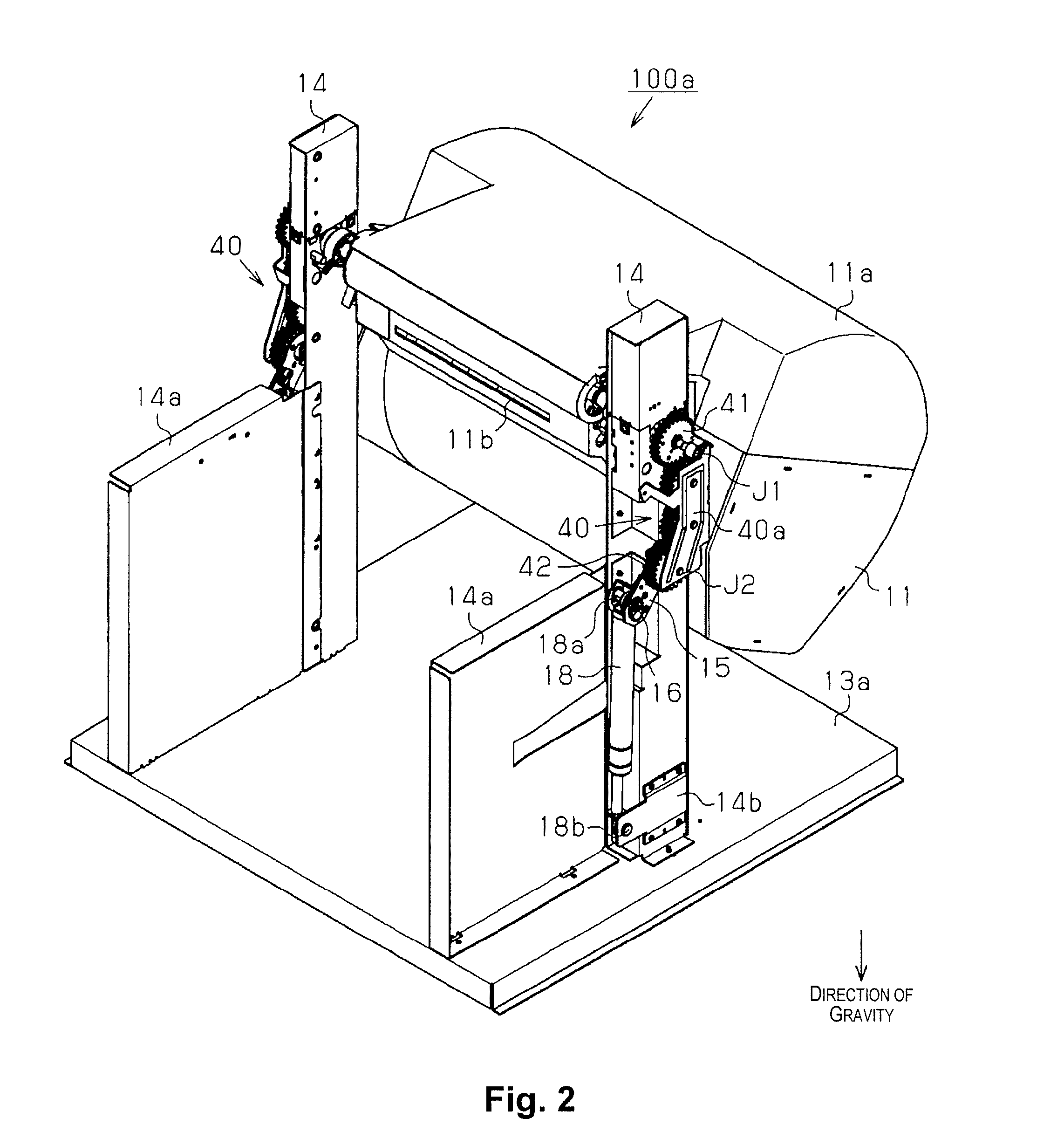
[0050]FIG. 2 is a perspective view showing the configuration of a roll paper accommodation device 100a of the first embodiment. Except for the roll paper accommodation device 100a, there are no depictions of structural elements associated with the printer 10. In the description hereinbelow, the direction of gravity is sometimes referred to as “down” or “downward,” and the direction opposite that of gravity is sometimes referred to as “up” or “upward.”

[0051]The roll paper accommodation device 100a is configured from a roll paper accommodation unit 11, and mechanical components for swinging the roll paper accommodation unit incorporated within a casing 13 (not shown). The configuration thereof is described hereinbelow.

[0052]First, the tray 12 (not shown) is provided with a sliding base part 13a in the top surface, and the base part 13a is provided with two support braces 14 which are stood upright and separated so that the tray 12 can be accommodated between partitioning plates 14a pr...

second embodiment

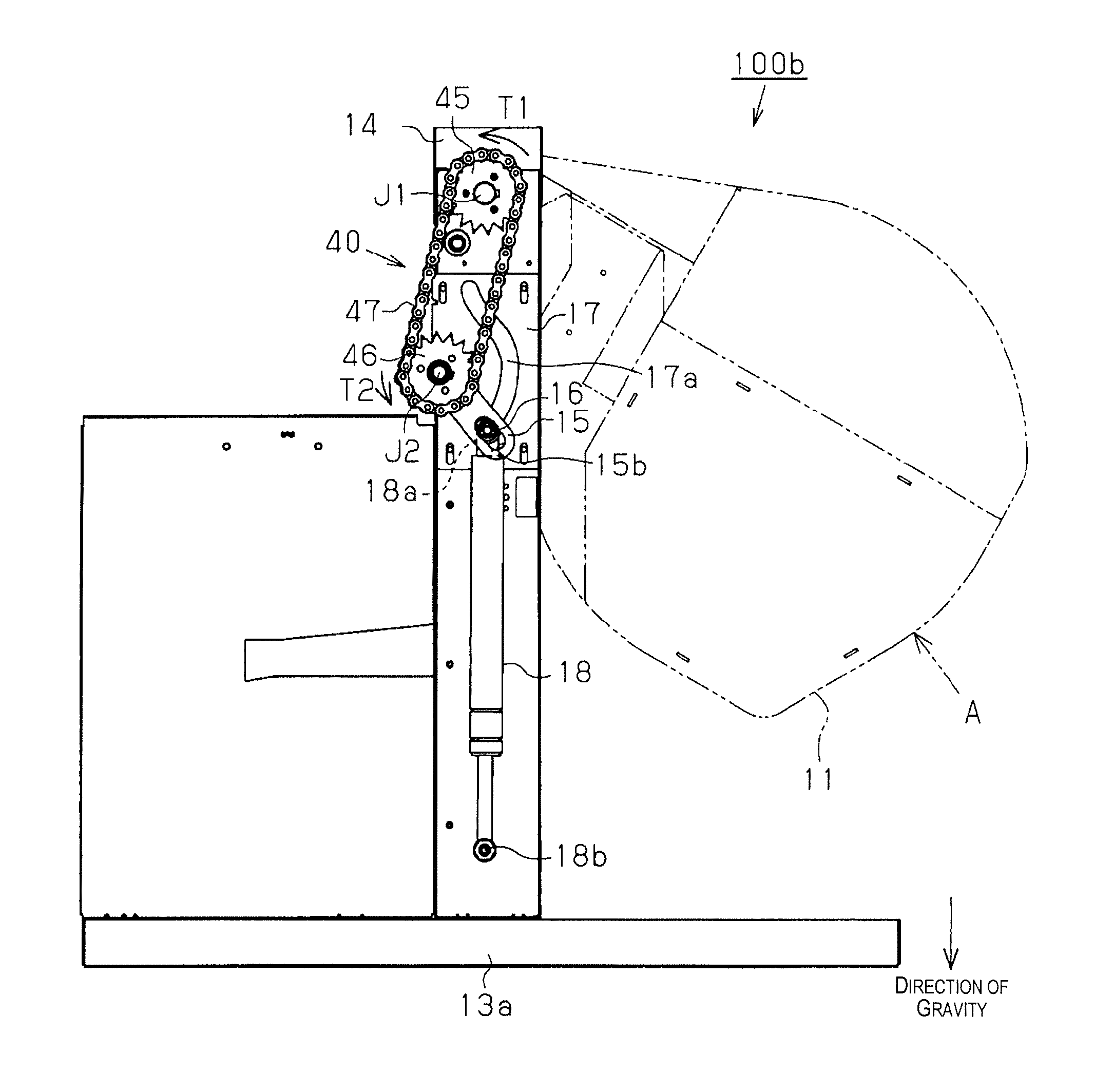
[0081]Next, the second embodiment will be described. The second embodiment is a roll paper accommodation device having a configuration that uses a chain instead of spur gears as the rotation-transmitting unit 40 in the first embodiment. It is also a roll paper accommodation device configured so that the movement of the shaft member 16 in the lever member 15 described in the first embodiment is performed by another member.

[0082]FIG. 6 is a side view showing the configuration of a roll paper accommodation device 100b of the second embodiment, and is a drawing equivalent to FIG. 3 described in the first embodiment above. Structural elements identical to those of the first embodiment are denoted by the same symbols, and descriptions thereof are omitted. Structural elements associated with the printer 10 are also not shown. In the description hereinbelow, similar to the first embodiment, the direction of gravity is sometimes referred to as “down” or “downward,” and the direction opposite...


PUM


Abstract

A rolled medium accommodation device includes a rolled medium accommodation unit which swings around a first shaft, a lever member which swings around a second shaft in conjunction with swinging of the rolled medium accommodation unit, a shaft member capable of moving in a direction intersecting an axial direction of the second shaft, and urging unit configured to apply rotational torque around the second shaft to the lever member. Due to the rotational torque, the rolled medium accommodation unit is subjected to force whereby the rolled medium accommodation unit is swung in a direction opposite that of gravity around the first shaft from a low position to a high position higher than the low position, and the shaft member moves so that the distance between a center of the shaft member and a center of the second shaft is greater in the high position than in the low position.

Description

CROSS-REFERENCE TO RELATED APPLICATIONS[0001]This application claims priority to Japanese Patent Application No. 2010-046290 filed on Mar. 3, 2010. The entire disclosure of Japanese Patent Application No. 2010-046290 is hereby incorporated herein by reference.BACKGROUND[0002]1. Technical Field[0003]The present invention relates to a rolled medium accommodation device and a liquid ejection device comprising this rolled medium accommodation device.[0004]2. Related Art[0005]There are known liquid ejection devices in which a liquid (e.g. ink) is ejected from a liquid ejection head and deposited onto a recording medium (paper or the like), whereby a predetermined image (including letters, pictures, and the like) is printed on the paper. In this type of liquid ejection device, in cases of large-scale printing requiring numerous sheets of paper or cases of performing elongated printing with a long printing range in the paper conveying direction, the paper must be continuously supplied to t...

Claims


Application Information

Patent Timeline
Patent Type & Authority Patents(United States)
IPC IPC(8): B41J2/01
CPCB41J2/01B41J15/04B41J15/042B65H19/126B65H2403/70B65H2402/31B65H2402/441B65H2801/06B65H2801/12
Inventor YAMAYA, KEISUKE
Owner SEIKO EPSON CORP
Why Eureka
Try Eureka