Eureka AIR delivers breakthrough ideas for toughest innovation challenges, trusted by R&D personnel around the world.

Boat propelling system

a technology of propelling system and propeller, which is applied in the direction of underwater vessels, non-deflectable wheel steering, electric devices, etc., can solve the problems of increasing the gap between the first information and the second information, reducing operation accuracy, etc., and achieving the effect of determining the operation accuracy of the transmission mechanism

Active Publication Date: 2012-12-25
YAMAHA MOTOR CO LTD
View PDF16 Cites 3 Cited by
  • Summary
  • Abstract
  • Description
  • Claims
  • Application Information

AI Technical Summary

Benefits of technology

[0007]Preferred embodiments of the present invention provide a boat propelling system that is capable of determining operation accuracy of a transmission mechanism.
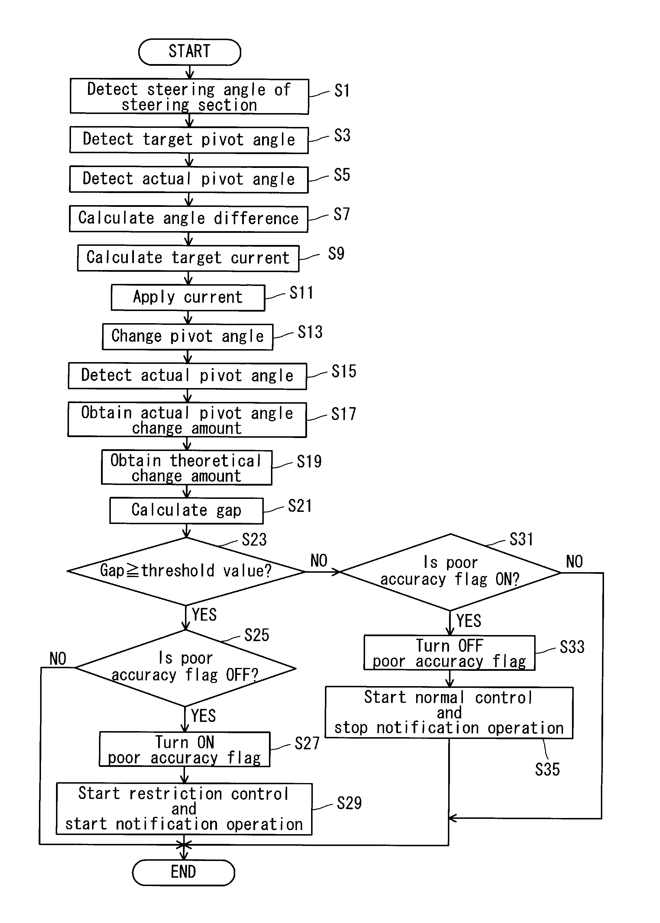
[0009]In a preferred embodiment of the present invention, the first information regarding an actual pivot angle change amount of the propelling system main body is obtained based on a result of detection made by the actual pivot angle detection section while the second information regarding a calculated theoretical pivot angle change amount of the propelling system main body is obtained based on a drive amount of the electric motor. Under a normal state, the electric motor drive amount and the actual pivot angle change amount are in a proportional relationship in accordance with a predetermined transmission ratio of the transmission mechanism. Hence, it is possible to obtain a normal-state, calculated theoretical pivot angle change amount by multiplication between the electric motor drive amount and the predetermined transmission ratio of the transmission mechanism. The calculated theoretical pivot angle change amount described above is indicated by the second information, and if a comparison between the first information and the second information reveals a large gap between the two, it is determined that operation accuracy of the transmission mechanism has decreased due to deterioration from wear or the like. By comparing the first information and the second information as described, the system can easily determine operation accuracy of the transmission mechanism.
[0010]Preferably, the boat propelling system further includes a locking member which is provided more on the transmission mechanism side than is the electric motor, to lock the transmission mechanism to prevent the propelling system main body from being pivoted in the right-left direction by a force exerted on the propelling system main body. In this case, the locking member locks the transmission mechanism when the propelling system main body receives an external force. This prevents the propelling system main body from being pivoted in the right-left direction. This eliminates the need for supplying electric power constantly to the electric motor, making it possible to reduce electric power consumption. Since the locking member such as described is provided more on the transmission mechanism side than is the electric motor, decrease in operation accuracy of the locking member, which may be caused by deterioration from wear, etc., will also increase the amount of gap between the first information and the second information. Hence, operation accuracy of the transmission mechanism and locking member can be determined easily by comparing the first information and the second information.
[0011]Further preferably, the transmission mechanism includes a buffer member arranged to absorb an impact. In this case, it is possible to reduce deterioration of the transmission mechanism caused by wear, etc., since the buffer member absorbs impacts which act on the transmission mechanism as the propelling system main body receives external forces. Therefore, it is possible to reduce decrease in the operation accuracy of the transmission mechanism. In other words, it is possible to extend the life of the transmission mechanism.
[0012]Further, preferably, the boat propelling system includes a control section arranged and programmed to control an output of the propelling system main body based on a result of determination by the determination section. In this case, an output from the propelling system main body is restricted to reduce the boat speed if there is a determination that operation accuracy of the transmission mechanism has decreased. This prevents the hull from deviating excessively from an intended direction of travel even under a situation where the operation accuracy of the transmission mechanism has decreased and there is an increased gap between the target pivot angle and the actual pivot angle. In general, when the propelling system main body has a greater output and the boat speed is higher, the boat has a greater yaw rate. In other words, when the propelling system main body has a greater output and the boat speed is higher, the boat turns well even if the pivot angle is small. Preferred embodiments of the present invention therefore provide an advantage particularly when the propelling system main body has a high output.

Problems solved by technology

Since the locking member such as described is provided more on the transmission mechanism side than is the electric motor, decrease in operation accuracy of the locking member, which may be caused by deterioration from wear, etc., will also increase the amount of gap between the first information and the second information.

Method used


Image

  • Boat propelling system
  • Boat propelling system
  • Boat propelling system

Examples


Embodiment Construction

[0023]Hereinafter, preferred embodiments of the present invention will be described with reference to the drawings.

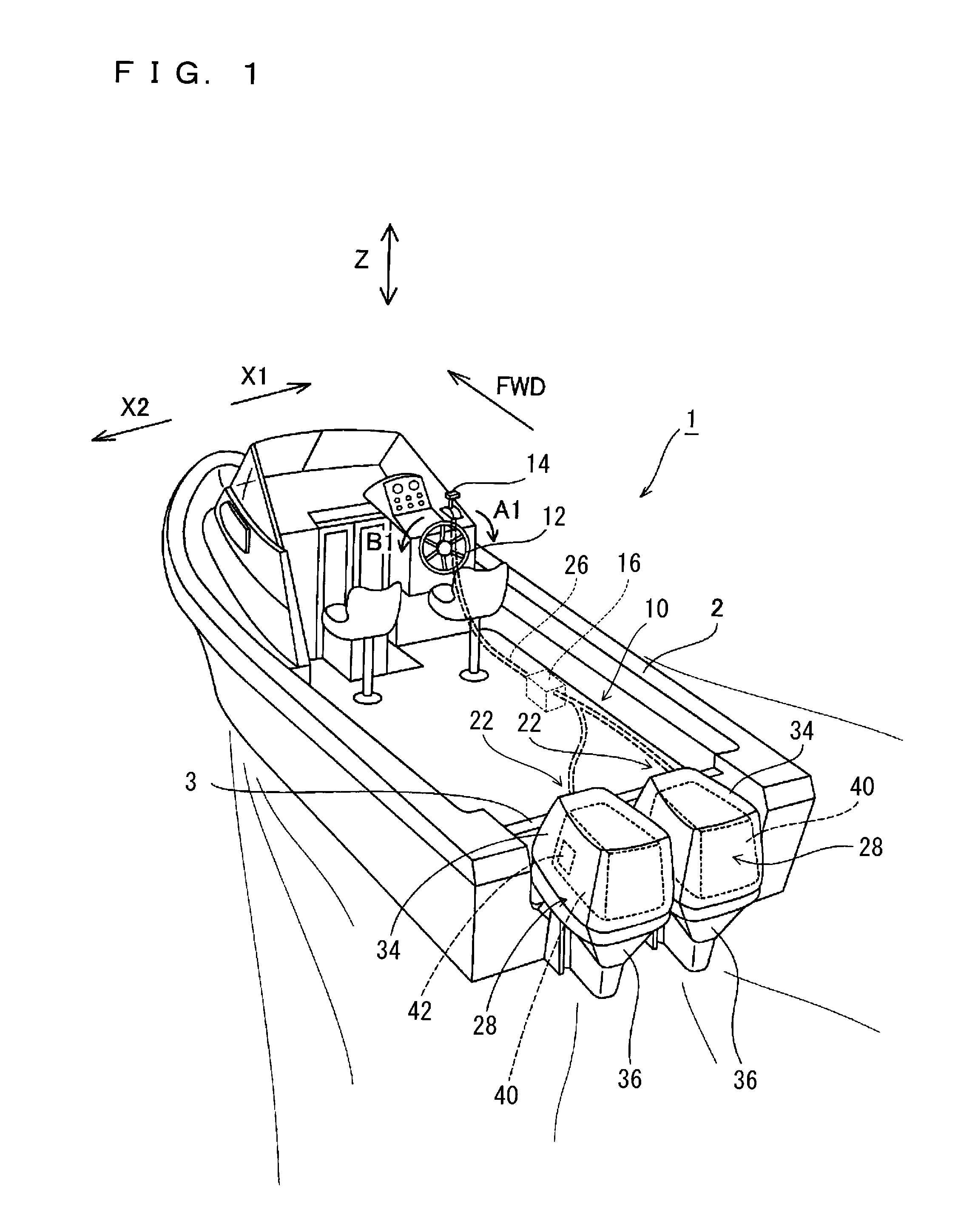
[0024]The description will cover a case where a boat propelling system 10 according to a preferred embodiment of the present invention is installed in a boat 1. A symbol “FWD” which appears in some of the drawings indicates a forward traveling direction of the boat 1.

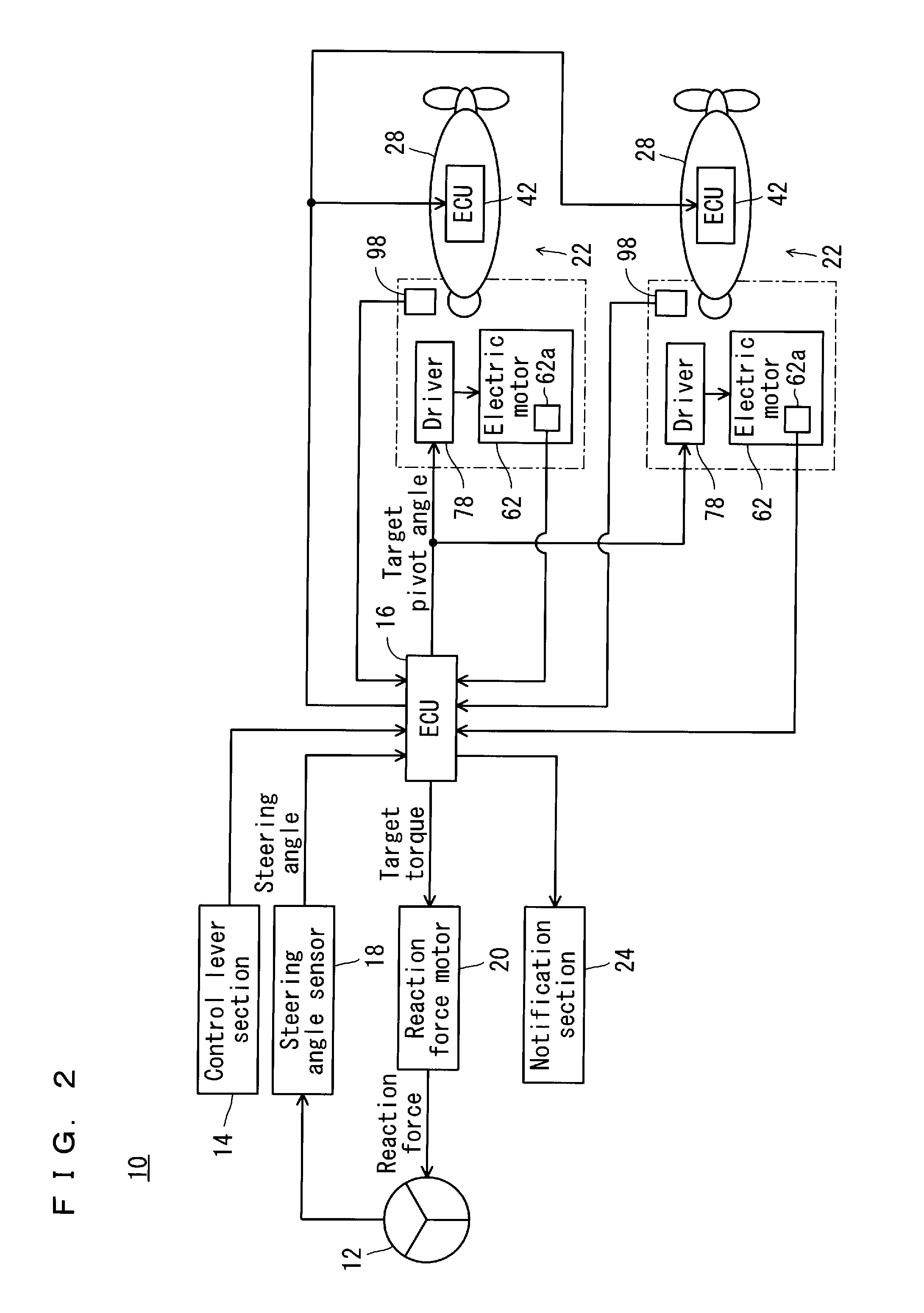
[0025]Referring also to FIG. 2, the boat 1 includes a hull 2 and a boat propelling system 10 installed on the hull 2.

[0026]The boat propelling system 10 includes a steering section 12 arranged inside the hull 2 to steer outboard engine main bodies 28 (to be described later); a control lever section 14 arranged near the steering section 12 to perform a forward-moving or rearward-moving operation of the hull 2; an ECU (Electronic Control Unit) 16 arranged and programmed to control operations of the boat propelling system 10; a steering angle sensor 18 arranged to detect a steering angle of a rotating operatio...


PUM


Abstract

A boat propelling system capable of determining operation accuracy of a transmission mechanism includes an outboard engine main body, a swivel bracket arranged to allow the outboard engine main body to pivot in a right-left direction with respect to a hull, an electric motor provided in the swivel bracket to pivot the outboard engine main body in the right-left direction, a pivot sensor provided in the electric motor to detect a pivot angle of a motor shaft, a transmission mechanism provided in the swivel bracket to transmit a driving force of the electric motor to the outboard engine main body, a pivot sensor arranged to detect an actual pivot angle of the outboard engine main body, and an Electronic Control Unit arranged and programmed to control an operation of the boat propelling system.

Description

BACKGROUND OF THE INVENTION[0001]1. Field of the Invention[0002]The present invention relates to boat propelling systems, and more specifically, to a boat propelling system including an electric motor arranged to pivot a propelling system main body in a right-left direction with respect to the hull.[0003]2. Description of the Related Art[0004]As disclosed in JP-A 2006-199189, for example, use of an electric motor to pivot an outboard engine (propelling system main body) in a right-left direction with respect to a hull for steering the hull is a conventional technique.[0005]According to the technique in JP-A 2006-199189, a target pivot angle of a propelling system main body (e.g., outboard engine main body) which pivots with respect to the hull, is set by using a steering wheel turning angle or the like. Then, based on an angle difference between an actual pivot angle and the target pivot angle of the outboard engine, a drive amount of an electric motor is determined and the electric...

Claims


Application Information

Patent Timeline
Patent Type & Authority Patents(United States)
IPC IPC(8): B60G17/018B62C3/00B62K25/00G06F7/00G06F17/00B60G23/00A01B69/00G05D1/02B62D11/00B60W10/04B63H21/22B63H25/02B63H20/00B63H25/42
CPCB63H21/22
Inventor MIZUTANI, MAKOTOHAYAMI, RYUTA
Owner YAMAHA MOTOR CO LTD
Why Eureka
Eureka Blog
Learn More