
Wireless sensor network and method for performing communication therein

a sensor network and wireless sensor technology, applied in the field of wireless communication technology, can solve the problems of wasting battery power, deteriorating data transmission efficiency from the upper node to the lower node, and worsening problems

Inactive Publication Date: 2012-12-25
IND ACADEMIC COOPERATION FOUND KYUNG HEE UNIV +1
View PDF2 Cites 4 Cited by
  • Summary
  • Abstract
  • Description
  • Claims
  • Application Information

AI Technical Summary

Benefits of technology

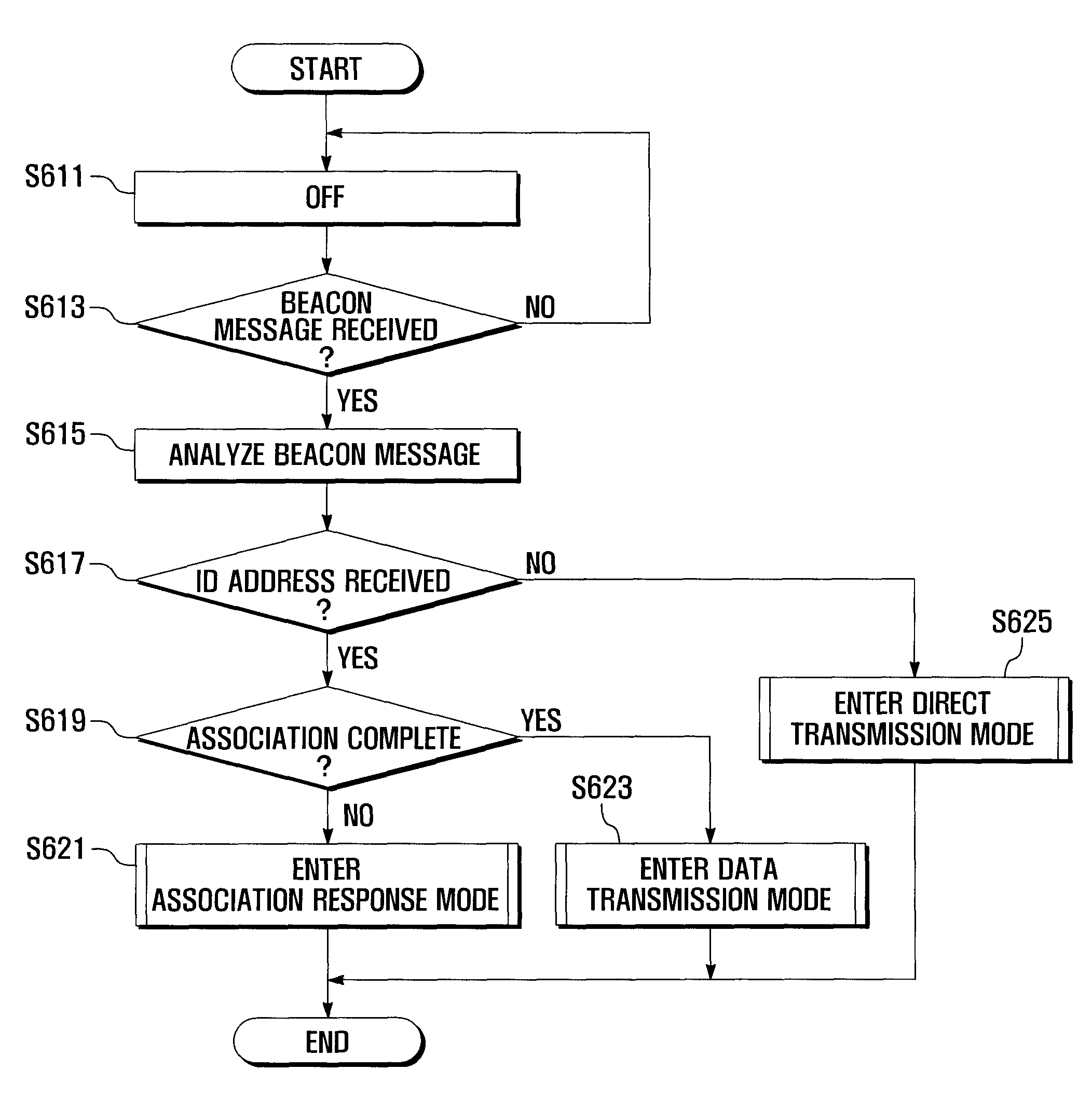
The present invention provides a wireless sensor network and a method for communication between an upper node and a plurality of lower nodes. The upper node transmits a beacon message to the lower nodes, which distinguishes an indirect transmission interval and a direct transmission interval. During the indirect transmission interval, the upper node transmits downlink data to the lower nodes, while during the direct transmission interval, the upper node receives uplink data from the lower nodes. The lower node detects the indirect transmission interval and the direct transmission interval from the received beacon message, and transmits the uplink data to the upper node in the direct transmission interval. This allows for sequential transmission of data between the upper and lower nodes, improving communication efficiency and reliability in the wireless sensor network.

Problems solved by technology

Since the lower nodes request data from the upper node based on competition-based channel linking, the efficiency of data transmission deteriorates from the upper node to the lower nodes.
Therefore, the upper node and the lower nodes waste battery power.
This problem worsens as the number of lower nodes communicating with the upper node increases.

Method used


Image

  • Wireless sensor network and method for performing communication therein
  • Wireless sensor network and method for performing communication therein
  • Wireless sensor network and method for performing communication therein

Examples


Embodiment Construction

[0023]Exemplary embodiments of the present invention are described in detail with reference to the accompanying drawings. The same reference numbers are used throughout the drawings to refer to the same or similar parts. For the purposes of clarity and simplicity, detailed descriptions of well-known functions and structures incorporated herein may be omitted to avoid obscuring the subject matter of the present invention.

[0024]Prior to explaining the embodiments of the present invention, terminologies are defined for the present description as follows:

[0025]The term “downlink data” refers to data that is collected by the upper node and provided from the upper node to the lower nodes. The term “uplink data” refers to data that is collected by the lower node and provided from the lower nodes to the upper node. The term “indirect transmission mode” refers to a mode wherein the upper node transmits messages or data to the lower nodes through a wireless sensor network only when the upper ...


PUM


Abstract

A method for performing communication in the wireless sensor network is disclosed. The upper node transmits a beacon message to the lower nodes, wherein the beacon message distinguishes an indirect transmission interval, in which the upper node transmits downlink data to the plurality of lower nodes, from a direct transmission interval adjacent to the indirect transmission interval, in which the upper node receives uplink data from the plurality of lower nodes. The lower nodes determine the indirect transmission interval and the direct transmission interval from the received beacon message. The downlink data is transmitted from the upper node to the lower nodes in the indirect transmission interval. The uplink data is transmitted from the lower nodes to the upper node in the direct transmission interval. When communication is performed between the upper node and the lower nodes, the data can be efficiently transmitted from the upper node to the lower nodes.

Description

CLAIM OF PRIORITY[0001]This application claims the benefit of the earlier filing date, pursuant to 35 USC 119, to that patent application entitled “WIRELESS SENSOR NETWORK AND METHOD FOR PERFORMING COMMUNICATION THEREIN” filed in the Korean Intellectual Property Office on Dec. 13, 2007 and assigned Serial No. 2007-0129880, the contents of which are incorporated herein by reference.BACKGROUND OF THE INVENTION[0002]The present invention relates to wireless communication technology, and more particularly, to a wireless sensor network having an upper node that periodically transmits a beacon message and at least one lower node that communicates with the upper node in response to the received beacon message.[0003]In general, wireless sensor network technology is classified into wireless local area network (WLAN) technology and wireless personal area network (WPAN) technology according to the recognition distance thereof. WLAN is based on IEEE 802.11 and enables devices to be connected to...

Claims


Application Information

Patent Timeline
Patent Type & Authority Patents(United States)
IPC IPC(8): H04W84/02
CPCH04W74/04H04W48/08H04W84/18H04W74/006H04W52/02H04L12/28
Inventor KIM, EUI JIKKIM, SUN GICHOI, HYO HYUNKIM, JEONG GEUNPHAN, VAN CA
Owner IND ACADEMIC COOPERATION FOUND KYUNG HEE UNIV
Learn More