
Communication device and high-frequency coupler

a communication device and high-frequency coupler technology, applied in the direction of resonant antennas, near-field systems using receivers, instruments, etc., can solve the problems of low frequency, difficult to expect a dramatic increase in the future, and extreme slowness compared with other general-purpose wireless communication

Inactive Publication Date: 2012-12-25
SONY CORP
View PDF19 Cites 6 Cited by
  • Summary
  • Abstract
  • Description
  • Claims
  • Application Information

AI Technical Summary

Benefits of technology

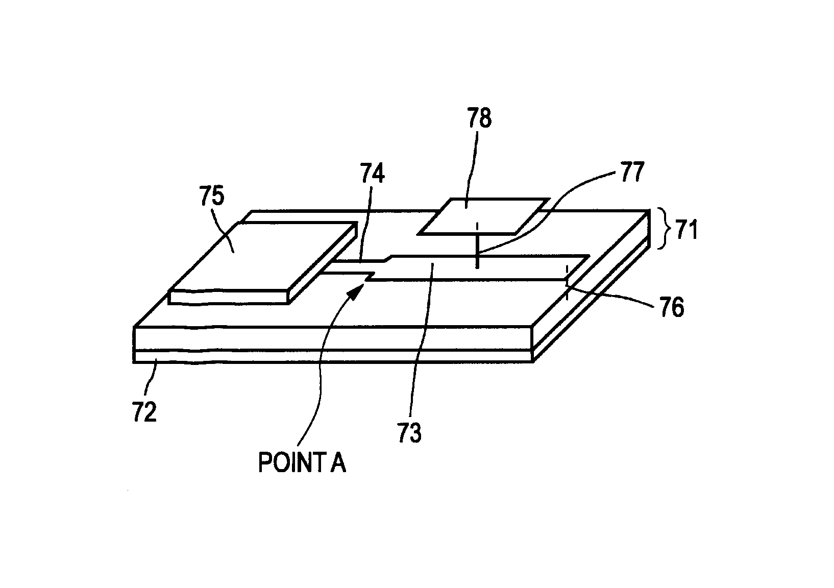
The present invention provides an excellent communication device and high-frequency coupler of low height that can perform large-capacity data transmission in close proximity through a weak UWB communication technique using a high-frequency wide band. The coupler includes a transmission path, a ground, a coupling electrode, and a resonating unit. The resonating unit increases the current flowing into the coupling electrode, and a microdipole is formed of a line segment connecting the coupling electrode and the ground. The resonating unit has a phase length of approximately ½ wavelength and is designed to face the communication device with an angle of approximately 0 degree. The coupler is supported by two terminals, which ensures sufficient mechanical strength and prevents deterioration in electric characteristics even at low height. The resonating unit can be formed of a first and second resonating unit, and a cut-out portion is provided to suppress a current not flowing through the coupling electrode. The first and second resonating units have an almost same phase length, which further enhances the performance of the coupler.

Problems solved by technology

However, the communication rate in NFC communication, which is a typical example of non-contact communication, is approximately 106 kbps to 424 kbps, which is sufficient for personal authentication or billing process but is extremely slow compared with other general-purpose wireless communication (such as WiFi and Bluetooth).
Thus, it is difficult to expect a dramatic increase in rate in the future.
As with the non-contact IC tag described above, when the communication device is implemented on an information device for use, it can be one of important technical problems to lower the height of the weak UWB communication device.

Method used


Image

  • Communication device and high-frequency coupler
  • Communication device and high-frequency coupler
  • Communication device and high-frequency coupler

Examples


Embodiment Construction

[0052]Embodiments of the present invention are described below with reference to the drawings.

[0053]First, the operation principle of near-proximity high-speed wireless communication using a weak UWB communication technique is described.

[0054]FIG. 1 schematically illustrates the structure of a near-proximity high-speed wireless communication system of a weak UWB communication technique using an electric-field coupling action. In FIG. 1, a transmitter 10 and a receiver 20 have a coupling electrode 14 and a coupling electrode 24, respectively, for use in transmission and reception. These coupling electrodes 14 and 24 are disposed so as to face each other and be separated from each other by, for example, 3 cm, thereby allowing electric-field coupling. Upon a transmission request from a higher-level application, a transmission circuit unit 11 on a transmitter 10 generates a high-frequency transmission signal, such as a UWB signal, based on transmission data, and propagates the generated...


PUM


Abstract

A communication device includes a communication circuit unit, a transmission path, a ground, a coupling electrode, and a resonating unit. The resonating unit includes a first resonating unit connected to the transmission path and a second resonating unit having one end connected to the first resonating unit and another end short-circuited to the ground, the second resonating unit having terminals of the coupling electrode connected thereto. A microdipole is formed of a line segment connecting a center of charges stored in the coupling electrode and a center of mirror-image charges stored in the ground. The high-frequency signal is transmitted to a distant side disposed so as to face the communication device with an angle θ formed relative to a direction of the microdipole being approximately 0 degree.

Description

BACKGROUND OF THE INVENTION[0001]1. Field of the Invention[0002]The present invention relates to communication devices and high-frequency couplers for large-capacity data transmission in close proximity through a weak UWB communication technique using a high-frequency wide band and, in particular, to a communication device and high-frequency coupler of low height.[0003]2. Description of the Related Art[0004]Non-contact communication has been widely available as a medium for authentication information, electronic money, and other value information. Examples of an IC card standard complying with ISO / IEC 14443 include Type A, Type B, and FeliCa®. Furthermore, near field communication (NFC) developed by Sony Corporation and Koninklijke Philips Electronics N.V. is an RFID standard mainly defining specifications of an NFC communication device (reader / writer) communicable with an IC card of each of Type A, Type B, and FeliCa. In NFC, with the use of a band of 13.56 MHz, non-contact bidirec...

Claims


Application Information

Patent Timeline
Patent Type & Authority Patents(United States)
IPC IPC(8): H01P5/00H01Q9/04G06K19/07G06K19/077H01P1/203H01P5/02H01Q1/50H01Q9/28H04B5/48
CPCH01P5/028H01Q9/0407H04B5/02H04B5/22H04B5/48
Inventor WASHIRO, TAKANORI
Owner SONY CORP
Learn More