Self-positioning dental light filtering device

a self-positioning, dental technology, applied in the field of dental equipment, can solve the problems of compromising efficiency, affecting the use of filtering members, and affecting the efficiency of care providers,

Active Publication Date: 2012-12-25
MACE JAMES GORDON
View PDF27 Cites 14 Cited by
  • Summary
  • Abstract
  • Description
  • Claims
  • Application Information

AI Technical Summary

Benefits of technology

[0008]This invention is directed to a self-positioning dental light filtering device. In one embodiment, the light filtering device comprises a transparent filter member for blocking optically harmful light emitted from a tip of a dental curing device, and a support for supporting the filter member in an upright position above the tip of the curing device. The filtering device also includes a rotational bearing having concentric outer and inner components rotatable relative to one another about an axis of rotation. The outer component is immovable relative to the support and the inner component defines an opening for receiving the tip or other component of the dental curing device. A retaining device is provided for holding the tip or other component of the dental curing device substantially centered inside the rotational bearing and substantially rotationally stationary relative to the inner component of the rotational bearing when the tip or other component is received in the opening. A counterweight below the rotational bearing causes the filter member to remain in its upright position when the tip of the curing device and / or curing device itself is rotated about said axis of rotation.

Problems solved by technology

This is disadvantageous in several ways.
First, the time taken to reach for the filtering member and hold it in place compromises efficiency since the dental assistant could be performing other duties while the dentist is curing.
Also, the filtering member can sometimes be forgotten and not used, leaving the care provider's eyes vulnerable to the optically harmful light.
Furthermore, the filtering members are typically large and cumbersome to store and use.
However, the cone can interfere with placement of the tip in the correct position, can push matrix systems (which are sometimes precariously placed) out of their correct positions, and allows the optically harmful light to leak out of the perimeter of the cone.
The disadvantage of this type of tool is that it continually needs to be adjusted to get it into the right position as the curing light is maneuvered around the mouth.
Furthermore, when attempting to cure teeth in the very back of the mouth, this type of filtering disc can interfere with tip placement by pressing against the face of the patient and need to be adjusted to allow proper tip placement.
In summary, all of these implements have drawbacks and are difficult to use.
Some clinicians choose simply not to use a filtering device because no great options are on the market.
The care providers are therefore at risk from the optically harmful light.
This leads to inaccuracies in tip placement which sometimes require another cure in the correct position and / or short exposures to harmful light if the curing begins prior to looking away.

Method used


Image

  • Self-positioning dental light filtering device
  • Self-positioning dental light filtering device
  • Self-positioning dental light filtering device

Examples


Embodiment Construction

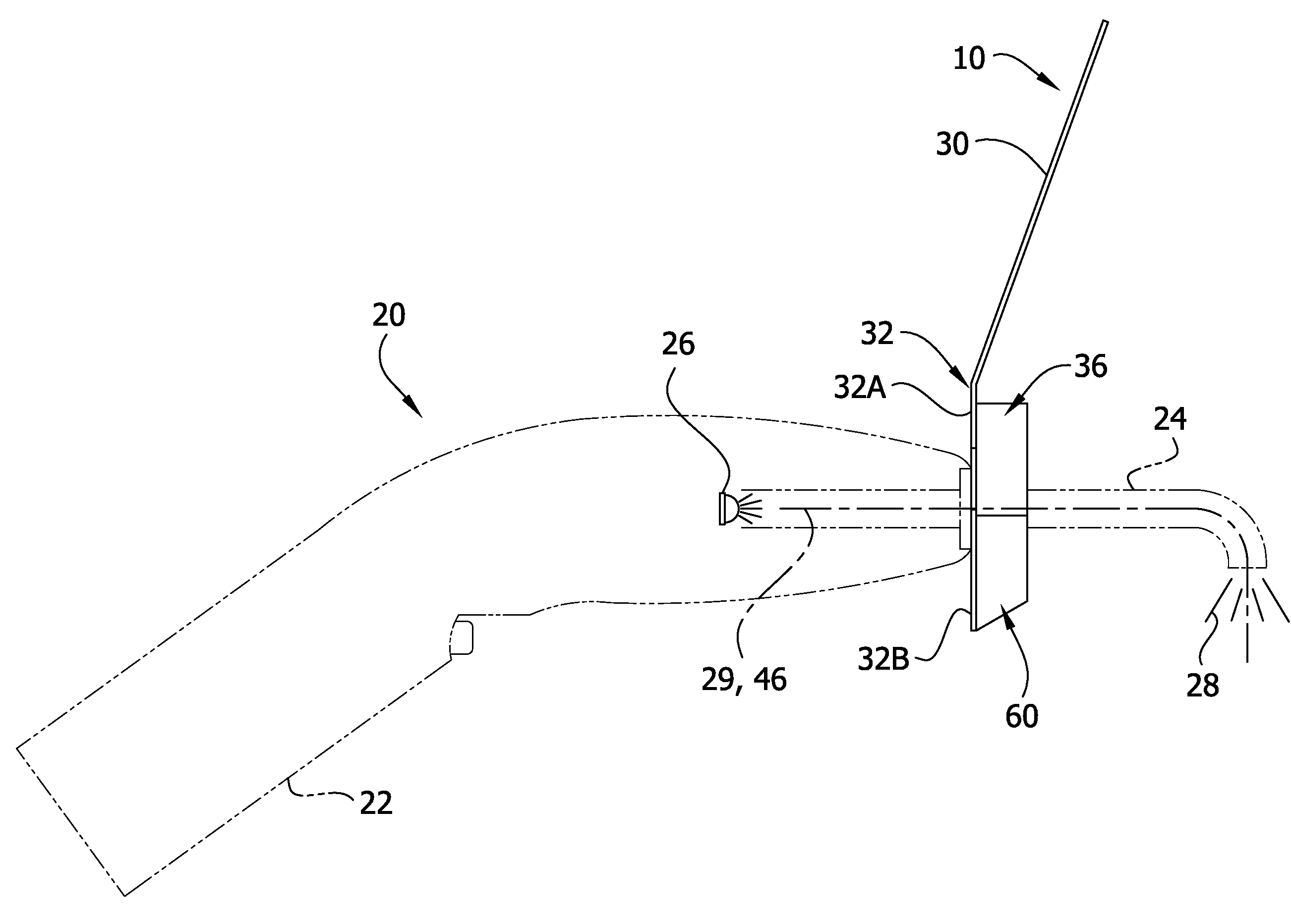
[0016]Referring now to the drawings, FIG. 1 illustrates one embodiment of a self-positioning dental light filtering device of this invention, generally designated 10. The light filtering device 10 is configured to be mounted on the tip or other component of a dental curing device for blocking optically harmful light emitted from the tip of the device. A conventional dental curing device, generally designated 20, is depicted in phantom lines in FIG. 2. The curing device has a body 22 formed as a handle to be gripped by the care provider (e.g., dentist), and an elongate tip 24 extending forward from the body. The body 22 is equipped with a light-emitting device 26, such as an LED, that emits a curing light 28 through the tip 24, as will be understood by those skilled in the field of dentistry. Typically, the tip 24 can be rotated (manually) relative to the body 22 of the curing device 20 about the longitudinal axis 29 of the tip. The curing device 20 forms no part of this invention an...


PUM


Abstract

A self-positioning dental light filtering device is disclosed. The filtering device includes a transparent filter member for blocking optically harmful light emitted from a tip of a dental curing device, and a rotational bearing having an inner component defining an opening for receiving the tip. A retaining device holds the tip substantially centered inside the rotational bearing and substantially rotationally stationary relative to the inner component of the rotational bearing. A counterweight below the rotational bearing causes the filter member to remain in an upright position above the tip when the tip of the curing device and / or curing device itself is rotated.

Description

CROSS-REFERENCE TO RELATED APPLICATION[0001]This application is a non-provisional patent application and claims priority from U.S. Provisional Patent Application Ser. No. 61 / 572,089, filed Jul. 11, 2011, which is incorporated herein by reference.FIELD OF THE INVENTION[0002]The present invention generally relates to dental equipment, and more particularly to dental equipment used for eye protection.BACKGROUND OF THE INVENTION[0003]Various implements have been employed in dentistry to shield the eyes of the dentist and other care providers from the optically harmful light emitted from dental curing devices. The most commonly used implements are described below.[0004]One implement comprises a handheld filtering member that is held over the patient's mouth while the composite is cured. This is disadvantageous in several ways. First, the time taken to reach for the filtering member and hold it in place compromises efficiency since the dental assistant could be performing other duties whi...

Claims


Application Information

Patent Timeline
IPC IPC(8): A61C1/00
CPCG02B7/006G02B5/22A61C19/004
Inventor MACE, JAMES GORDON
Owner MACE JAMES GORDON
Why Eureka
Try Eureka