Fixing device and image forming apparatus

a technology of fixing device and image forming apparatus, which is applied in the direction of electrographic process apparatus, ohmic resistance heating, instruments, etc., can solve the problems of reducing image quality, affecting image quality, and affecting image quality, so as to prevent the occurrence of creases on the belt surface and prevent the occurrence of uneven gloss on the prin

Active Publication Date: 2012-12-11
KONICA MINOLTA BUSINESS TECH INC
View PDF10 Cites 2 Cited by
  • Summary
  • Abstract
  • Description
  • Claims
  • Application Information

AI Technical Summary

Benefits of technology

[0021]In an image forming apparatus including a fixing device for fixing an image by a nip portion formed by two rotary members rotating opposite to each other, the slack of both ends of the belt occurring when one of the two rotary members is a belt rotating while being stretched around a plurality of rollers and among the plurality of rollers, the roller arranged at the exit of the nip portion has a crown shape is eliminated.
[0022]As a result, the occurrence of creases on the belt surface is prevented and the occurrence of uneven gloss appearing on print is prevented.

Problems solved by technology

However, a separation roller for pressurizing the belt against the opposite rotary member at the exit of the nip portion is rotated under support at both ends of the shaft, so that it is bent in the axial direction, and the pressure of the belt against the opposite rotary member is not uniform, thus the pressure at the central part of the belt may be lower than that at both ends of the belt.
A problem arises that the image may be disordered due to ununiformity of the pressure in the axial direction.
However, the press roller is formed in the crown shape, thus the diameter of the press roller is different between the central part of the belt and both ends thereof and at the ends where the diameters are smaller than that at the central part, the belt is slacked and the slack may cause an occurrence of creases referred to as surface waviness on the surface of the belt.
Such creases appear on the image surface as uneven gloss and may cause a reduction in the image quality.

Method used


Image

  • Fixing device and image forming apparatus
  • Fixing device and image forming apparatus
  • Fixing device and image forming apparatus

Examples


Embodiment Construction

[0030]Hereinafter, the embodiment of the present invention will be explained with reference to the accompanying drawings. Further, the present invention is not limited to the present invention.

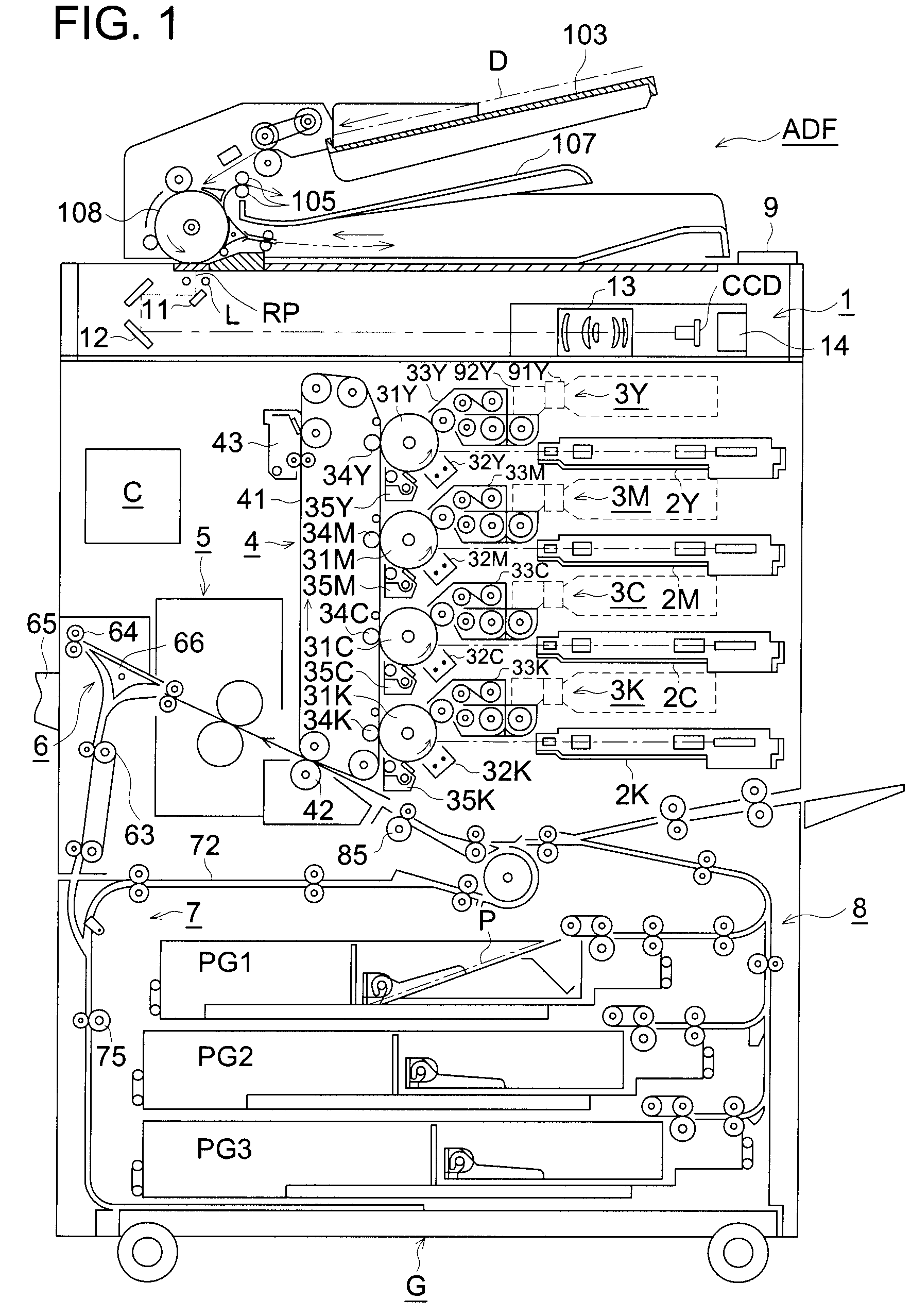
[0031]FIG. 1 is a conceptual diagram of an image forming apparatus G.

[0032]The color image forming apparatus G illustrated in the drawing is referred to as a tandem color image forming apparatus including a plurality of photoconductors 31Y, 31M, 31C, and 31K which are arranged in a column opposite to one intermediate transfer belt 41 for forming full color images.

[0033]The color image forming apparatus G includes an automatic document feeder ADF on the upper part thereof.

[0034]Documents D loaded on a document table 103 of the automatic document feeder ADF are separated one by one, are fed onto the document conveying path, and are conveyed by a conveying drum 108.

[0035]The images of the documents D under conveyance are read by a document reading unit 1 at a document image reading position RP. T...


PUM


Abstract

Provided is an image forming apparatus having a fixing device for fixing an image at a nip portion formed of two rotary members which rotate while facing each other, wherein occurrence of uneven print gloss is prevented. The image forming apparatus having a fixing device for fixing an image at a nip portion formed of two rotary members which rotate while facing each other, wherein one of the two rotary members is a belt which rotates while being stretched around of a plurality of rollers, a roller arranged at the exit of the nip portion out of the plurality of rollers has a crown shape, and a slack absorbing member for absorbing a slack of both ends of the belt caused by the crown-shaped roller is in contact with the belt.

Description

CROSS REFERENCE TO RELATED APPLICATIONS[0001]This application is a national phase application based on International Application No. PCT / JP2009 / 063733, filed Aug. 3, 2009, which claims the priority of Japanese Patent Application No. 2008-221038, filed Aug. 29, 2008, the content of both of which is incorporated herein by reference.FIELD OF THE INVENTION[0002]The present invention relates to a fixing device for heating a sheet carrying a toner image under pressure by conveying it, thereby fixing the toner image on the sheet and an image forming apparatus including the fixing device.PRIOR ART[0003]In an image forming apparatus such as an electrophotographic copying machine or a printer, in most cases, a sheet carrying a toner image is heated under pressure by a fixing device and the toner image is fixed onto the sheet.[0004]At one time, the fixing device generally fixes an image by conveying a sheet carrying a toner image by a nip portion formed by rollers which are rotary members arra...

Claims


Application Information

Patent Timeline
Patent Type & Authority Patents(United States)
IPC IPC(8): G03G15/20
CPCG03G15/2053G03G2215/2041
Inventor MARUKO, MASAMIKUROSU, TETSUKOHAMAYA, SATOSHI
Owner KONICA MINOLTA BUSINESS TECH INC
Why Eureka
Try Eureka