Apparatus for cutting the protective tape of semiconductor wafer

a technology for protective tapes and semiconductor wafers, which is applied in the direction of metal working equipment, chemistry apparatuses and processes, cable/conductor manufacturing, etc. it can solve the problems of defect of cutting, affecting the cutting effect, so as to achieve the same running cost and precise and accurate cutting of the tape

Inactive Publication Date: 2011-03-01
POLARIS ALPHA LLC +1
View PDF4 Cites 2 Cited by
  • Summary
  • Abstract
  • Description
  • Claims
  • Application Information

AI Technical Summary

Benefits of technology

[0023]In any of the above-described examples, stretching in an outside direction of the part of the protective tape on the traveling groove of the cutter can eliminate the wrinkles and wavy shape.
[0031]As an other embodiment, the tape tensioning device is provided with a pressing member disposed above the depression enabling free vertical movement, and thus descend of the pressing member deforms and inserts the protective tape into the depression.
[0034]In any of the above-described examples, function of a suitable tension to the projected part of the protective tape applied on the semiconductor wafer can provide precise and accurate cutting of the tape all over the peripheries of the semiconductor wafer. Moreover, the above-described examples eliminate the necessity of using a tensioning device, such as drawing in the outside direction by pinching of an end rim of the tape, in giving a tension to the projected part of the protective tape applied on the semiconductor wafer.
[0035]That is, the amount of the projected part of the protective tape applied on the semiconductor wafer does not necessarily need to be set larger, leading to use of the protective tape having only a minimum width and length. Therefore, operation with the same running cost of the protective tape as that in the conventional operation may be attained, resulting in practical great effectiveness.

Problems solved by technology

However, the part of the protective tape projected around the wafer fails to give a stable degree of stretch.
That is, cutting at a part having a weaker stretch of the protective tape may give wrinkles and wavy shape, and poor finish of the cut edge of the protective tape, leading to a defect of cutting resulting from disagreement of a starting position and an end position of cutting.
However, in a transverse direction perpendicularly intersecting to the travel of an application roller, there may be shown a tendency of giving a weaker stretch.
Therefore, poor finish easily occurs on the cut edge of the protective tape.
Therefore, the method possibly gives more amount of waste of the protective tape after cutting process, resulting in a disadvantage of higher running costs.

Method used


Image

  • Apparatus for cutting the protective tape of semiconductor wafer
  • Apparatus for cutting the protective tape of semiconductor wafer
  • Apparatus for cutting the protective tape of semiconductor wafer

Examples


example 1

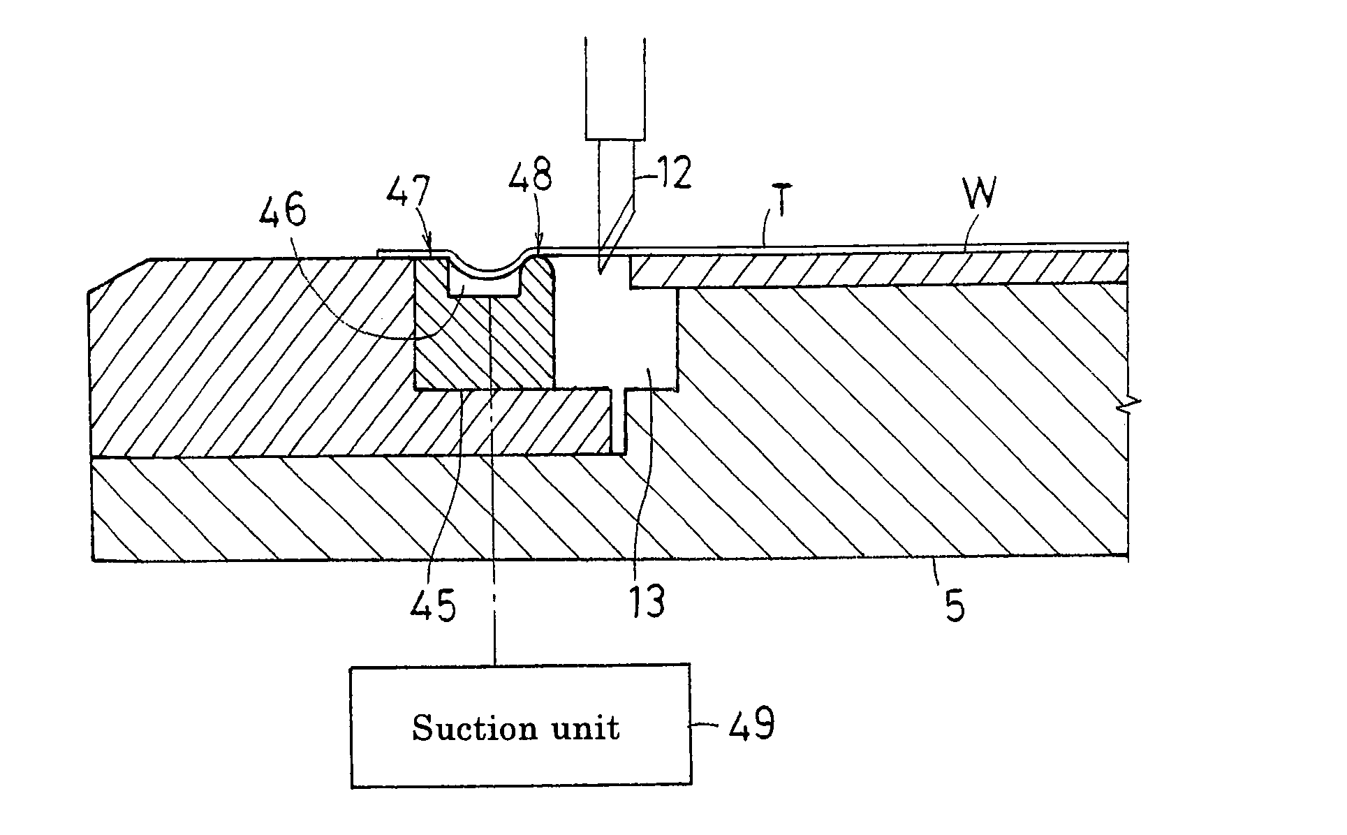
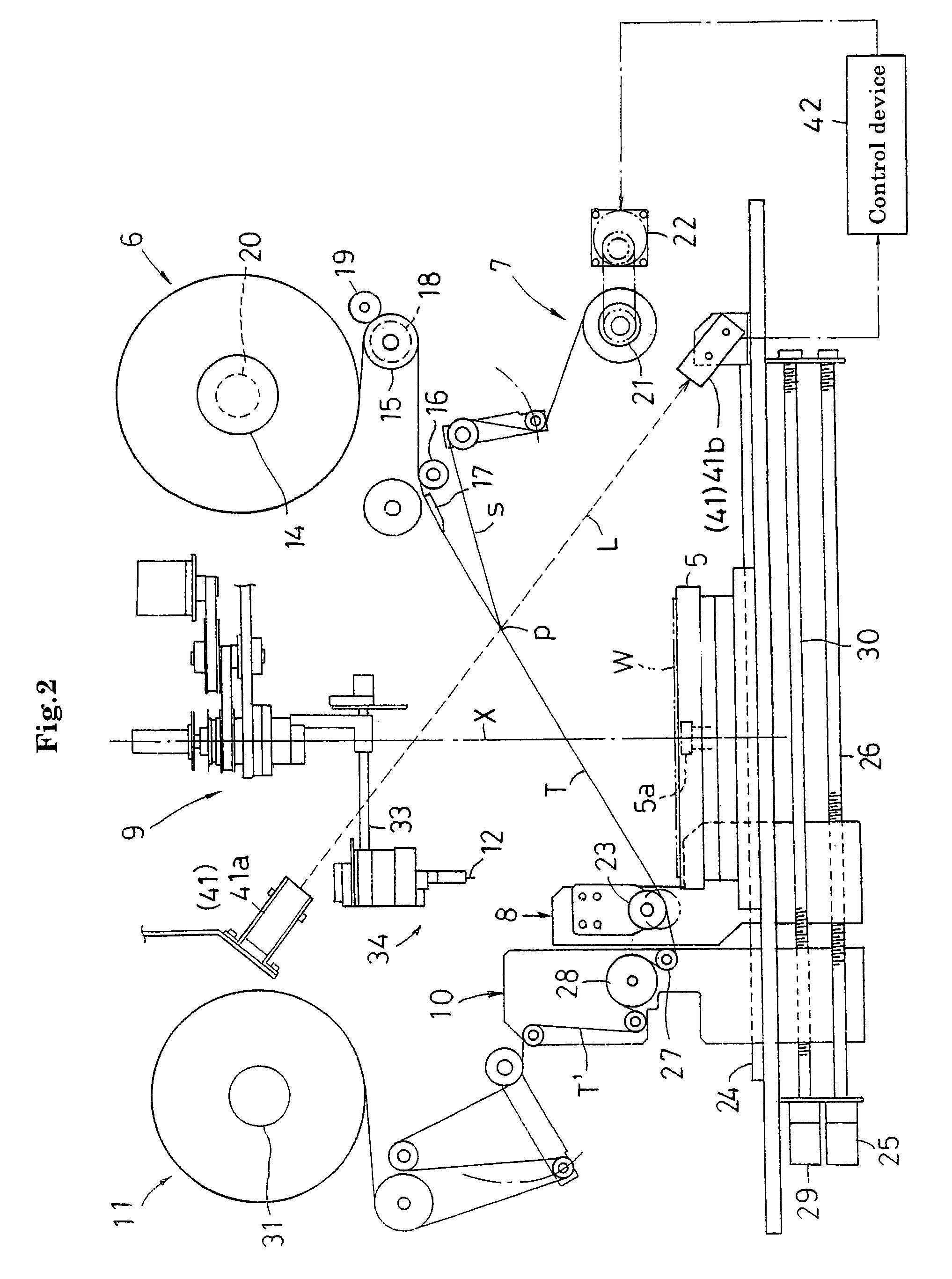
[0089]FIGS. 8 to 10 illustrates example 1 of a tape tensioning device. As illustrated in FIG. 8 and FIG. 9, a traveling groove for a cutter 13 formed on a top face of a chuck table 5 has a diameter of an inner circumference set somewhat smaller than the outside diameter of a wafer W. Accordingly, the wafer W is mounted so that the outer peripheral part of the wafer W may somewhat project from the traveling groove for the cutter 13.

[0090]The outer peripheral part, to which a protective tape T strongly applied, of the traveling groove for the cutter 13 has a ring member 45 disposed therein, as illustrated in FIG. 9. This ring member 45 is formed with stainless steel or aluminum materials.

[0091]The top face of this ring member 45 is set to give approximately the same height as the height of the surface of the wafer W mounted on the table. Furthermore, the outside diameter is set so that the protective tape T projecting from the wafer W may be applied over the outer edge of the ring mem...

example 2

[0098]FIG. 11 and FIG. 12 illustrate the second example of a tape tensioning device.

[0099]A chuck table 5 in this example has the same configuration as that of the example 1. That is, an annular depression 46 is formed through a ring member 45, and a tape holding section 47 and a tape supporting section 48 is formed in an outside and inside part of the depression 46. Furthermore, the depression 46 is communicatively connected with a suction unit 49.

[0100]A support plate 51 is fixed under a movable base 32 for ascending and descending a cutter blade 12. Spindles 53 are vertically and slidably inserted to guide tubes 52 suspended from three or four points in the circumferential direction of this support plate 51. Each spindle 53 is moderately biased downward with a spring 54 attached from outside, and limitation of the lowering position thereof is controlled with a stopper 55 that is equipped on the top end of the spindle 53 for allowing a position adjustment. A ring stay 56 is extend...

example 3

[0104]FIGS. 13 to 15 illustrate example 3 of the tape tensioning device.

[0105]A chuck table 5 in this example has the same configuration as that in the example 1. That is, while an annular depression 46 is formed through a ring member 45, a tape holding section 47 and a tape supporting section 48 are formed in an outside and inside part of a depression 46. Furthermore, the depression 46 is communicatively connected with a suction unit 49.

[0106]As illustrated in FIG. 13 and FIG. 15, a bracket 61 is fixed to a cutter unit 34 in an apparatus for cutting the tape 9. A pair of spindles 62 is vertically and slidably inserted into this bracket 61. A pressing roller 64 idling around a horizontal axis center Y that intersects with a vertical axis center X is equipped to a support component 63 extending between the lower ends of both the spindles 62. Each spindle 62 is moderately biased downward with a spring 65 attached from outside, and limitation of the lowering position thereof is control...


PUM

PropertyMeasurementUnit
adhesive propertyaaaaaaaaaa
pressureaaaaaaaaaa
pressuresaaaaaaaaaa

Abstract

An outer edge of a protective tape projected from a semiconductor wafer is fixed and held by a tape holding section. In the condition, a part of the projected protective tape is caught and supported with a tape supporting section with a face having lower adhesive property provided in the outside of the traveling groove for the cutter. Furthermore, the part of the protective tape having the outer edge fixed and held with the tape holding section is compulsorily deformed and inserted into a depression provided between the tape holding section and the tape supporting section. Thereby, the part of the protective tape located in a traveling groove for the cutter is tensioned outward. A cutter blade is stuck into this tensioned part, and cuts the protective tape all over the peripheries of the wafer.

Description

BACKGROUND OF THE INVENTION[0001](1) Field of the Invention[0002]The present invention relates to a method for cutting a protective tape applied on the surface of a semiconductor wafer that has been subjected to surface treatment, along with the periphery of the wafer, and relates to an apparatus for cutting the protective tape.[0003](2) Description of the Related Art[0004]For example, JP-A No. 2004-25438 discloses a following method as a method for cutting a protective tape applied on the surface of a semiconductor wafer (hereinafter, referred to as “wafer” for short).[0005]A protective tape is supplied on the surface of a wafer mounted and held on a chuck table, and then the protective tape is applied on the surface of the wafer by rotative travel of an application roller. Subsequently, the protective tape having a cutter blade stuck thereinto is rotated by rotation of the table (or the cutter blade is traveled), and thereby the cutter blade is rotated and traveled along with the ...

Claims


Application Information

Patent Timeline
Patent Type & Authority Patents(United States)
IPC IPC(8): B29C65/00B32B38/10B32B37/00B32B38/04H01B13/00H01L21/00
CPCB26D7/14B26F1/3846H01L21/67132B26D7/018Y10T156/1343Y10T156/1352Y10T156/1348Y10T156/12Y10T156/1357Y10T156/1361Y10T83/207Y10T83/0467Y10T83/323Y10T83/364H01L21/48
Inventor YAMAMOTO, MASAYUKIKANESHIMA, YASUJI
Owner POLARIS ALPHA LLC
Why Eureka
Try Eureka