
Method for virtual adaptation of an implant to a body part of a patient

a technology for virtual adaptation and implants, applied in the field of virtual adaptation of implants to the body parts of patients, can solve the problems of not being suitable for use in a procedure, limited to two-dimensional representations, and not being able to proceed automatically

Inactive Publication Date: 2012-12-11
SIEMENS HEALTHCARE GMBH
View PDF17 Cites 25 Cited by
  • Summary
  • Abstract
  • Description
  • Claims
  • Application Information

AI Technical Summary

Benefits of technology

[0012]An object of the present invention is to provide a method that allows an optimal adaptation of implants in more than two dimensions.
[0018]The desired (preferred) view then allows, for example, a best-possible optical monitoring of whether the object is actually optimally adapted to the body part at its end.
[0021]Since the object is shown in a desired manner, the method allows an improved, more precise monitoring at arbitrary points of the object and primarily also in the further environment of the object after an occurred automatic adjustment of the presentation on the screen.
[0023]Complete, nearly isotropic volume data sets (for example on the basis of computer tomography (CT)) are increasingly used as image material of patients and / or implants in medical technology. The inventive method is predominantly oriented on this. Such a “complete” three-dimensional data set possesses the advantages that they can be arbitrary visual navigation is possible in these data and that in every position the body structures (such as, for example, bones) are shown with full sharpness in a volume image without overlapping. The scaling is well-defined and reliable overall, constant over the entire volume and already attainable from the DICOM description of the data set. For real 3D representations it is necessary in the inventive method to implement the correct adaptation of the object by a transparent representation or by another technique of virtual immersion in the object volume. In this context MPR, volume rendering, MIP and SSD or 3D stereo representation are suitable as three-dimensional presentation formats on a screen. These methods are normally linked with a type of automatic clipping in order to ensure the precise adaptation inside the volume.

Problems solved by technology

Systems in which the x-ray image and / or the scale drawing of the implant already exist digitally represent an advance, but this case is predominantly limited to two-dimensional representations.
These known techniques, however, are not very suitable for use in a procedure and that is only two-dimensional, and they do not proceed automatically, least of all for repositioning (i.e. the reconstruction of, for example, a fragmented bone after a fracture).
From a modern point of view this is trivial and is limited to a procedure parallel to the table feed of the computed tomography apparatus.

Method used


Image

  • Method for virtual adaptation of an implant to a body part of a patient
  • Method for virtual adaptation of an implant to a body part of a patient
  • Method for virtual adaptation of an implant to a body part of a patient

Examples


Embodiment Construction

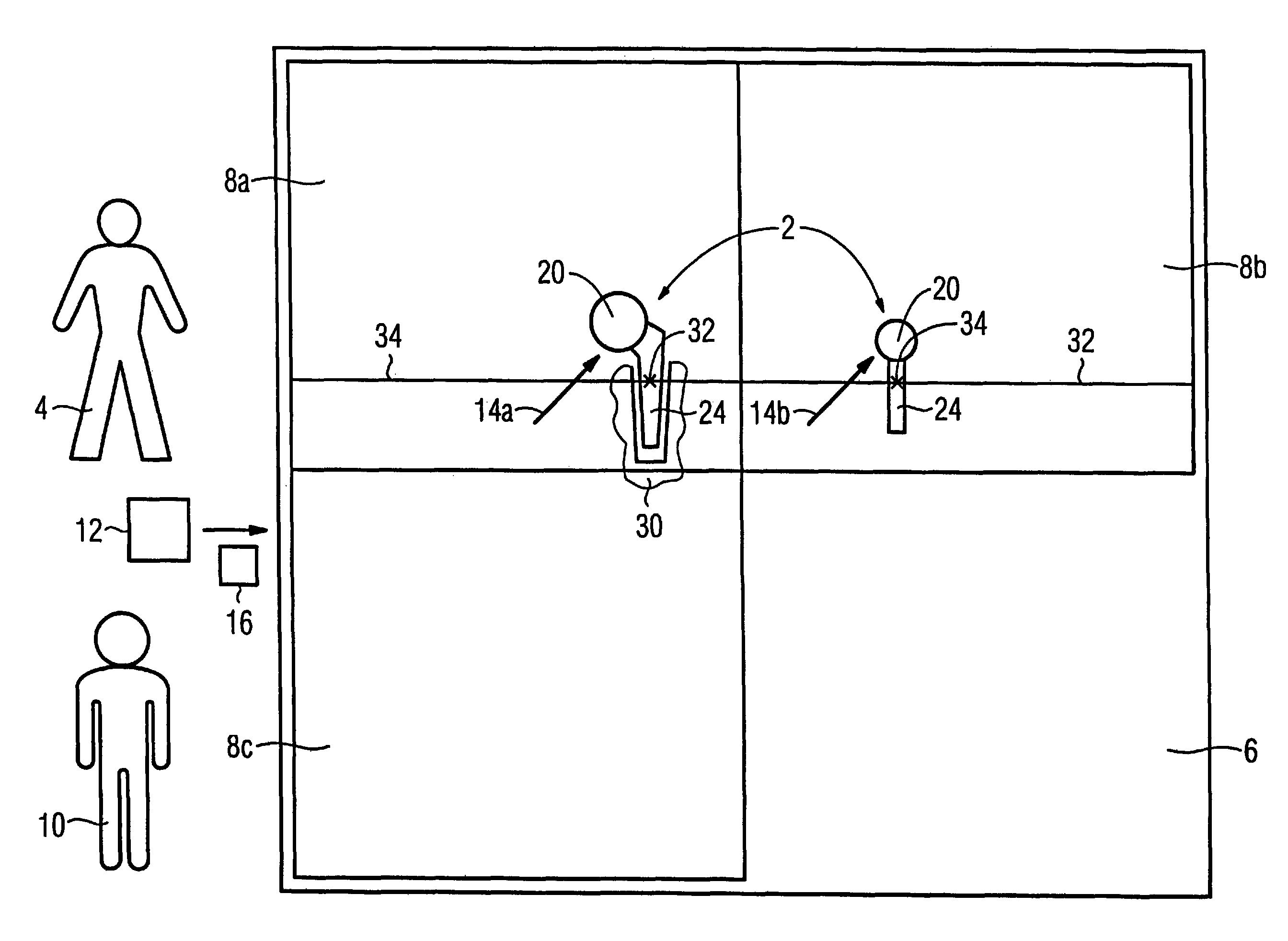
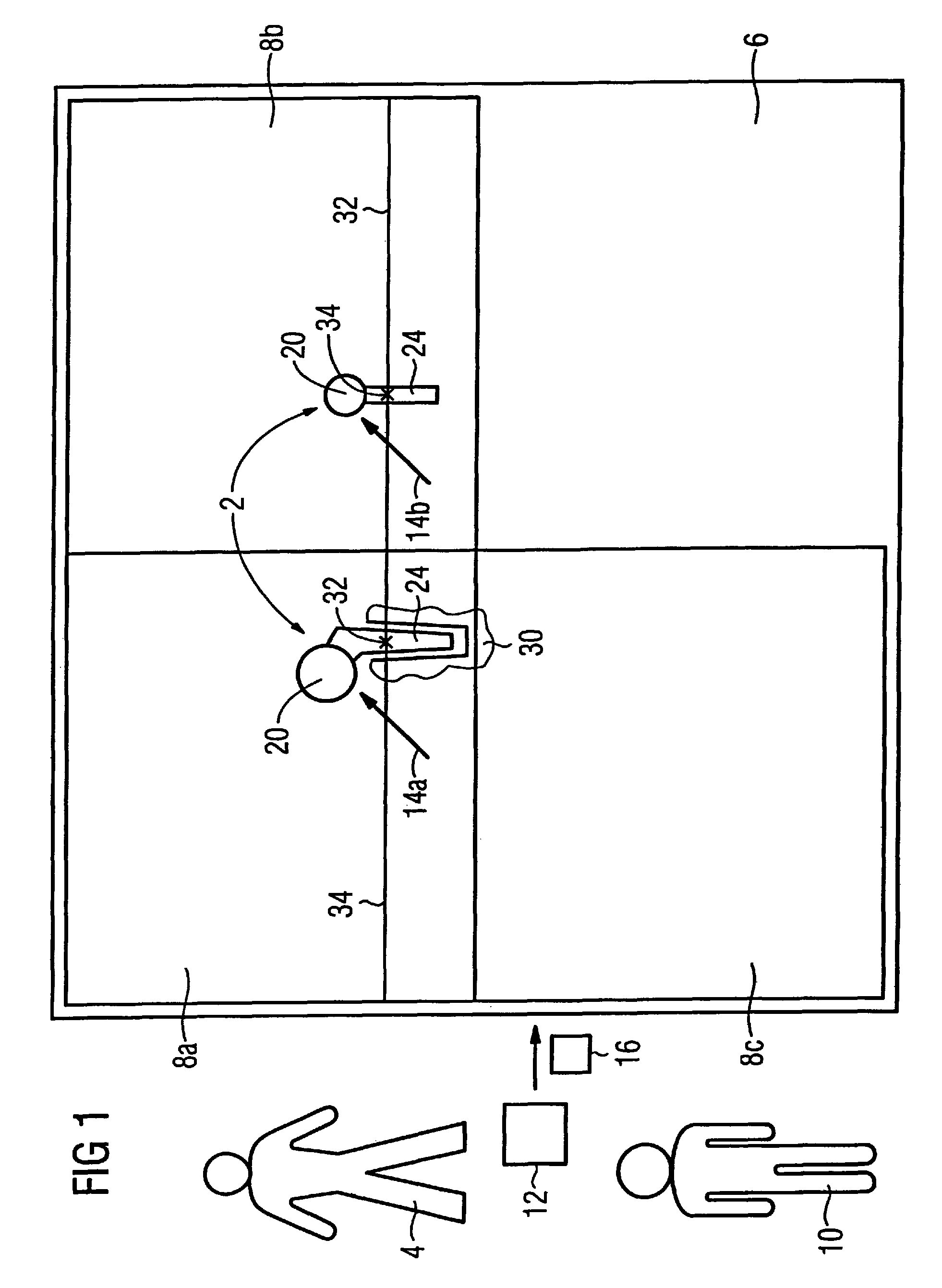
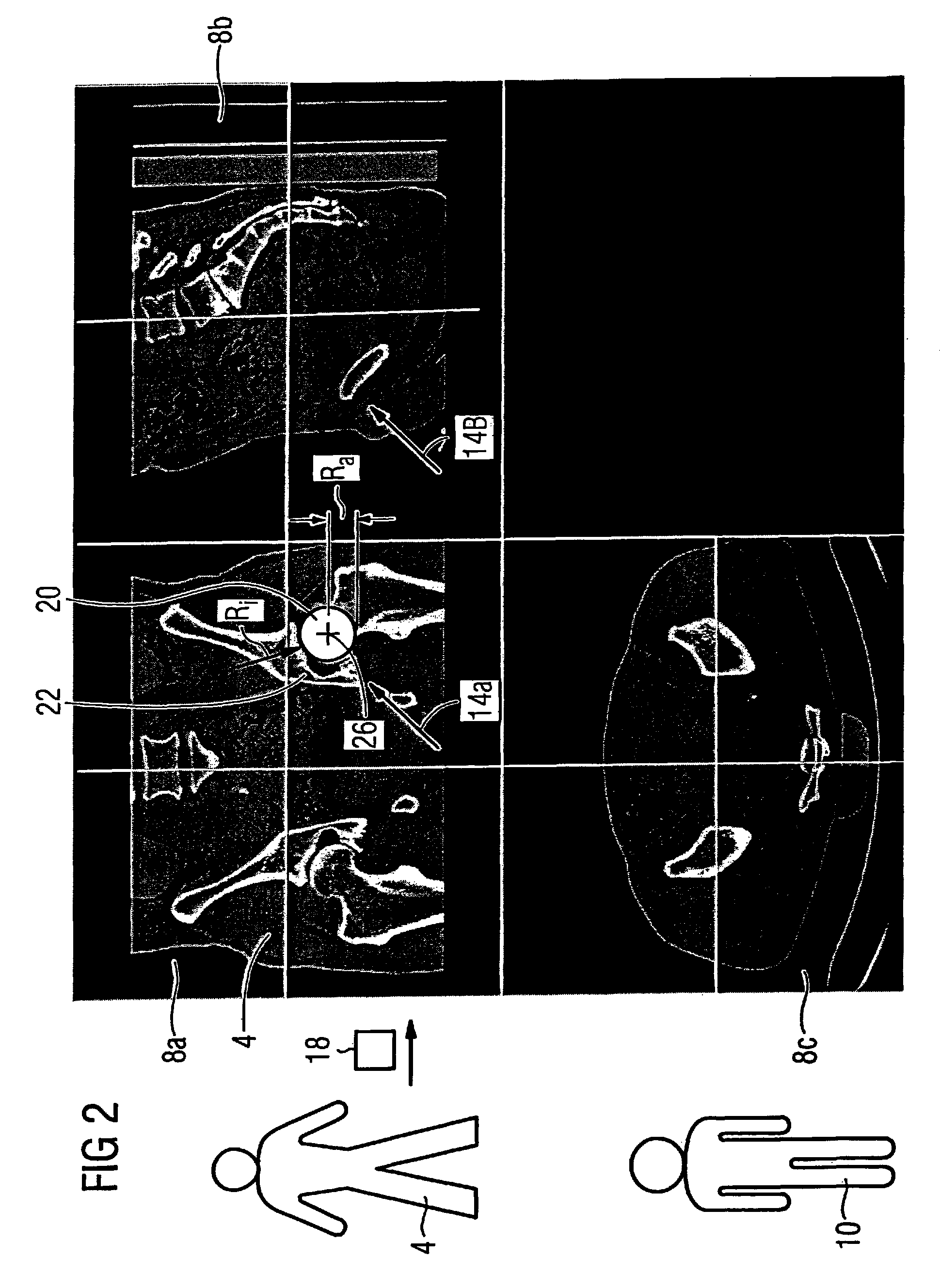
[0043]The following exemplary embodiment describes the virtual preoperative placement and adaptation of an artificial hip joint 2 as an object in a patient 4 by a physician 10. The method exemplarily operates with the MPR representation of image data on a monitor 6 of a medical operation planning workstation (CAD system) (not shown).

[0044]FIG. 1 shows the monitor 6 on which three windows 8a-c are shown. The windows 8a-c correspond to the arrangements of a frontal (8a), lateral (8b) and axial (8c) view that are typical for medical 3D views, for example for a patient-related image data. Operator of the method is the physician 10 who, dependent on the patient 4 (for example according to the patient's body size), selects a hip joint 2 deemed, from the size, as approximately fitting from a number of available hip joints in an implant database 12. For representation of the hip joint 2 on the monitor 6, its 3D image data 16 are taken from the database 12. The selected hip joint 2 is then p...


PUM


Abstract

In a method for virtual adaptation of an object to be medically inserted in a patient, to a body part of the patient, the object is shown in a desired view on a monitor, the body part is shown in 3D on the monitor, the body part in its unchanged 3D-imaging context, is automatically displaced relative to the object until the object is adapted to the body part with the orientation of the object relative to the monitor remaining unchanged.

Description

BACKGROUND OF THE INVENTION[0001]1. Field of the Invention[0002]The present invention concerns a method for virtual adaptation of an implant to a body part of a patient.[0003]2. Description of the Prior Art[0004]Today prostheses or implants that are inserted into patients are often used in surgery, in particular in orthopedic surgery. Strictly speaking, prostheses are normally replications or replacements for body parts of a patient; implants are mainly abstract components such as, for example, plates or screws. For simplification, however the term “implant” will be used herein to encompass both implants in the actual sense as well as prostheses.[0005]It is important to insert the implants into the patients with optimally exact fit and to optimally plan their insertion and to select a suitable implant for the insertion. Techniques derived, for example, from computer aided design (CAD) are increasingly required and utilized in the medical field for this purpose.[0006]In the predomina...

Claims


Application Information

Patent Timeline
Patent Type & Authority Patents(United States)
IPC IPC(8): G06K9/00A61F2/32
CPCA61B19/52G06T19/20A61B19/50A61B2019/501A61B2019/5289G06T2219/028G06T2219/2016A61B34/10A61B90/36A61B2034/101A61B2090/364
Inventor BARTH, KARLWESSELS, GERD
Owner SIEMENS HEALTHCARE GMBH
Learn More