Method of generating mesh for analysis

a mesh and analysis technology, applied in the field of generating a mesh pattern for analysis, can solve problems such as requiring a complicated operation, and achieve the effects of improving the quality of the surface mesh pattern, and improving the quality of the surface mesh

Active Publication Date: 2012-12-11
HITACHI LTD
View PDF8 Cites 2 Cited by
  • Summary
  • Abstract
  • Description
  • Claims
  • Application Information

AI Technical Summary

Benefits of technology

[0007]That is, according to the present invention, quality of a mesh pattern is evaluated temporarily created is evaluated according to a required quality and a correction is made by shifting a node point of a surface mesh according to the evaluation result so as to improve the mesh pattern, thereby obtaining a mesh pattern having no distortion and satisfying the required quality by automatic correction. Moreover, after a node point is shifted, internal meshes inside the object volume are created by the boundary element method so as to regenerate six-plane body meshes. Thus, by correcting a mesh on the surface, it is possible to correct distortion of the internal meshes all at once by correcting a mesh on the surface.
[0008]Here, the mesh quality includes an internal angle at each node point of the mesh, distortion of the mesh, a twist degree of the mesh, and the like. The internal angle is an angle defined by a pair of elementary segments, or lines constituting a mesh. If the internal angle near 90 degrees, the mesh has little distortion and approaches the target quality.
[0010]In this case, the mesh quality evaluation means further evaluates quality of internal meshes generated by the internal mesh means according to the required quality and the mesh correction means can shift a node point of an internal mesh not satisfying the required quality according to the evaluation result of the quality evaluation means, in the direction to improve the quality. Thus, it is possible to evaluate the mesh quality according to the required quality, make a correction by shifting a node point of a surface mesh according to the evaluation result, and correct internal meshes. This can generates a 3D mesh pattern satisfying the required quality without requiring a manual correction of a mesh.
[0011]Moreover, the mesh correction means calculates the shift direction and the shift amount of the node point to improve quality of the surface mesh pattern and can shift the node point so that the position of the node point after shifted is within a permissible range from the external surface and the external form line of the shape model.
[0012]Furthermore, the mesh correction means can select a node point of a mesh having an internal angle farthest from 90 degrees and calculate the shift direction and the shift amount of the node point so that the internal angle of the node point approaches 90 degrees. In this case, when the node point to improve the surface mesh quality is on the external surface or the external form line of the shape model, it is preferable that the mesh correction means shift the node point so that the node point after shifted is on the external surface or the external form line of the shape model. Furthermore, when the node point to improve the surface mesh quality is one of two node points on the external form line of the shape model, the mesh correction means can rotate, shift, or enlarge / reduce the line connecting the two node points so as to shift the node point to improve the quality and together with this, can shift node points existing on the line connecting the two node points on the external surface.
[0013]According to the present invention, it is possible to realize a device for generating a mesh pattern for analysis capable of automatically correcting a six-plane body mesh pattern satisfying the required quality.

Problems solved by technology

This requires a complicated operation.

Method used


Image

  • Method of generating mesh for analysis
  • Method of generating mesh for analysis
  • Method of generating mesh for analysis

Examples


Embodiment Construction

[0027]Description will now be directed to the best mode for carrying out the present invention.

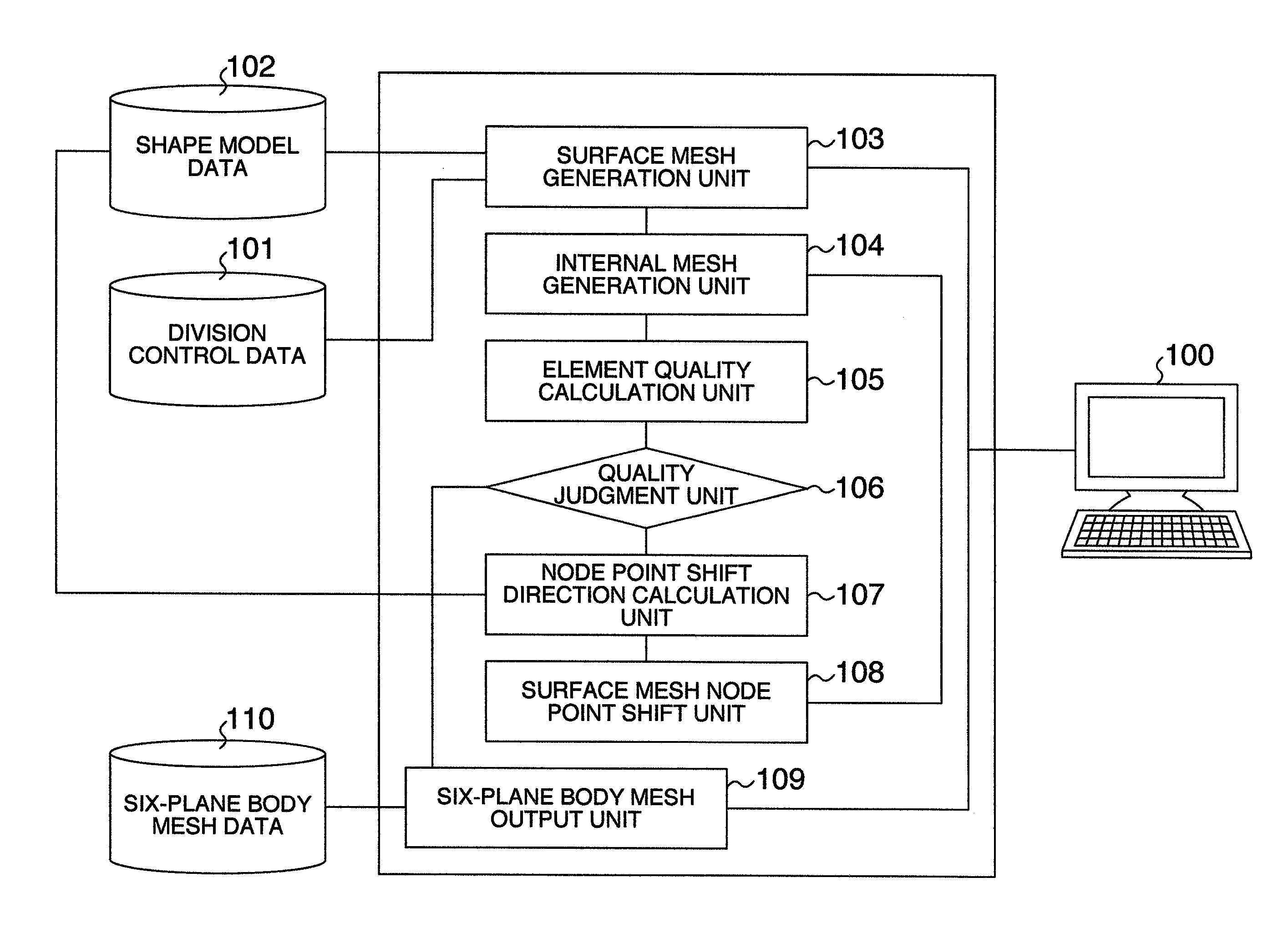
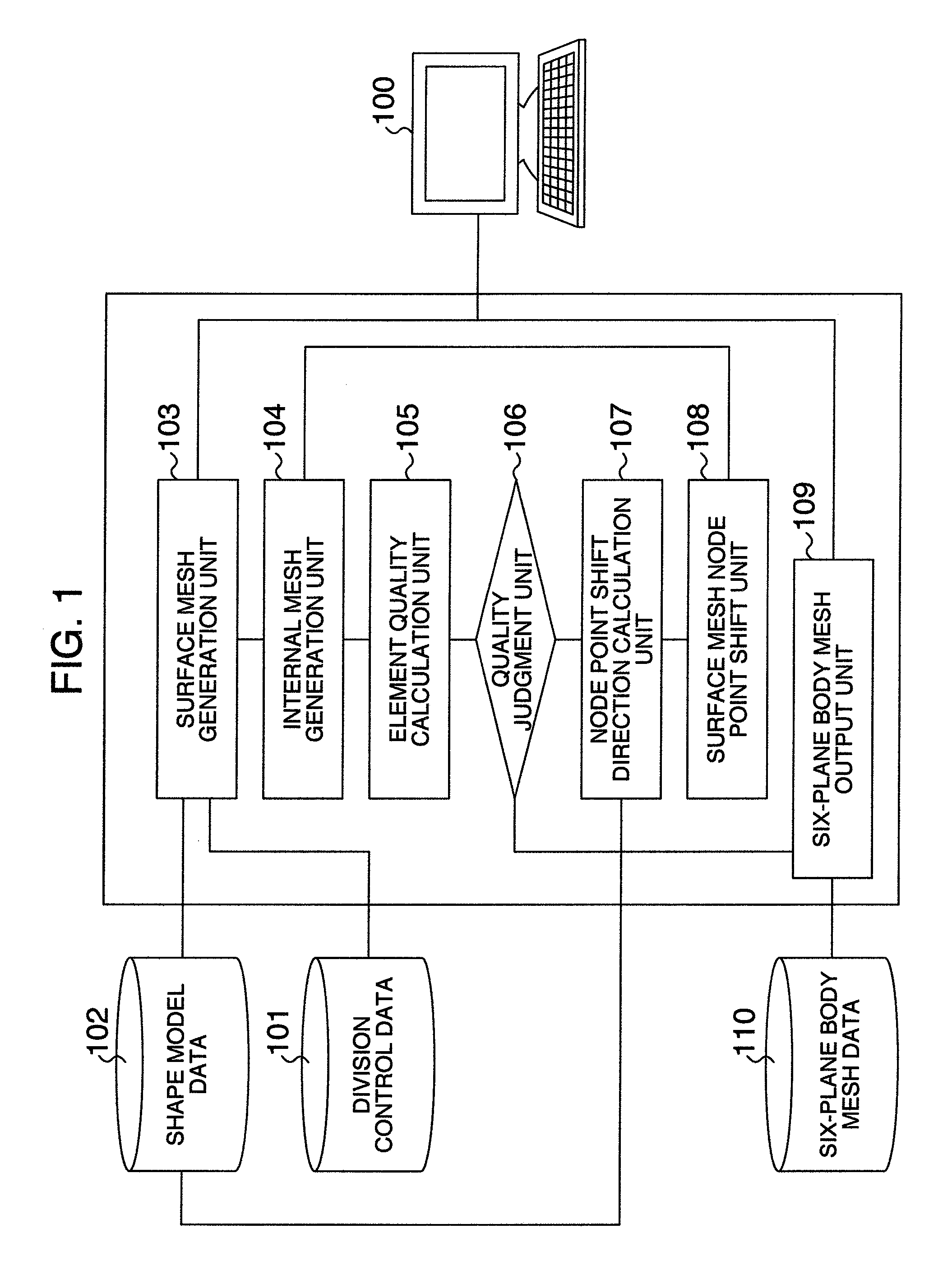
[0028]FIG. 1 shows an entire configuration of a device for generating a mesh pattern for analysis according to an embodiment of the present invention. As shown in the figure, the device for generating a mesh pattern for analysis according to the embodiment includes: a computer 100 having input means such as a keyboard, operation processing means, a display, and the like; storage means 101 for storing division control data as mesh control data; storage means 102 for storing shape model data on an object to be analyzed; and storage means 110 for storing generated six-plane body mesh data.

[0029]The operation processing means of the computer has a surface mesh generation unit 103, an internal mesh generation unit 104, an element quality calculation unit 105, a quality judging unit 106, a node point shift direction calculation unit 107, a surface mesh node point shift unit 108, and a six-plane ...


PUM


Abstract

It is possible to automatically correct a six-plane body mesh pattern so as to satisfy the required quality. A device for generating a mesh pattern for analysis comprises: surface mesh generating device for generating a surface mesh pattern of an analysis object by acquiring shape model data on the analysis object and mesh control data including required quality of an analysis mesh model; internal mesh generating device for generating an internal mesh pattern of the analysis object according to the generated surface mesh pattern; device for calculating the element quality of surface meshes; quality evaluating device for evaluating calculated element quality according to the required quality; and mesh correction device for shifting a surface mesh node point not satisfying the required quality in the direction to improve the quality.

Description

BACKGROUND OF THE INVENTION[0001]The present invention relates to a device for generating a mesh pattern for analysis and in particular, to a technique for automatically generating six-plane body mesh data satisfying a required quality from CAD (Computer Aided Design) data.[0002]The analysis using the finite element method divides an analysis object into small mesh elements each having a predetermined shape and acquires a change of a physical amount generated in each element of the mesh pattern. The method is widely used in structure analysis, thermal conduction analysis, fluid analysis, and the like. For example, it is known that as a mesh pattern for analysis, quadrangular meshes are generated on a surface of a shape model of the analysis object generated by the CAD and the internal portion is divided according to the quadrangular meshes so as to generate six-plane body (a cube or a rectangular parallelepiped) meshes for analysis.[0003]Moreover, as is disclosed in JP-A-9-311951, w...

Claims


Application Information

Patent Timeline
Patent Type & Authority Patents(United States)
IPC IPC(8): G06T17/00
CPCG06T17/20
Inventor KATAOKA, ICHIRONISHIGAKI, ICHIROHIRO, YOSHIMITSUHARIYA, MASAYUKI
Owner HITACHI LTD
Why Eureka
Try Eureka