Eureka AIR delivers breakthrough ideas for toughest innovation challenges, trusted by R&D personnel around the world.

Measurement apparatus and control method

a measurement apparatus and control method technology, applied in image enhancement, instruments, image data processing, etc., can solve problems such as unreliable position and orientation estimation, limited edge search range within captured images, and inability to obtain position and orientation efficiently

Active Publication Date: 2012-12-04
CANON KK
View PDF10 Cites 17 Cited by
  • Summary
  • Abstract
  • Description
  • Claims
  • Application Information

AI Technical Summary

Benefits of technology

The present invention provides a measurement apparatus and method that can efficiently measure the position and orientation of an image-capturing apparatus without being affected by the relative position between the image-capturing apparatus and the measurement object. This is achieved by acquiring a captured image of the measurement object, projecting geometric features of a 3D model of the measurement object onto the captured image, selecting the projection geometric features to be used in calculation of the position or orientation, and calculating the relative position or orientation of the image-capturing apparatus with respect to the measurement object using the selected projection geometric features and image geometric features. This technology can be used in various fields such as manufacturing, construction, and sports equipment design.

Problems solved by technology

In addition, during the above-mentioned estimation, the range of edge search within a captured image is limited to the image around the projected measurement line segments.
In real environments, the shadows etc. of measurement objects are often viewed as edges, which often makes position and orientation estimation unreliable.
However, problems arise when the image-capturing apparatus is combined with human motion, that is, when a person is holding the image-capturing apparatus itself and moving for the purpose of navigation, etc.
These problems are due to the fact that considerable changes take place in the relative position of the measurement object and the image-capturing apparatus when a person walks around a building or outdoors.
When the relative position of the observed object and image-capturing apparatus changes, problems arise in projection onto a captured image and geometric features of the measurement object.
However, the task that arises in environments such as corridors, where one can glance back, is to delay switching between multiple models.
Moreover, basically, it is difficult to detect segments smaller than one pixel in captured images.
For this reason, when proximate geometric features are far away, it becomes difficult to detect both image geometric features in the respective projection geometric features within a captured image, which affects the results of estimation.
At the same time, it becomes more difficult to implement efficient processing because image geometric feature search regions obtained from the proximate projection geometric features overlap.
Furthermore, nonlinear calculations have to be repeatedly carried out during optimization calculations used to obtain the position and orientation.
This is undesirable in mixed reality technology, which requires real-time processing at the video frame rate and accuracy of position and orientation.

Method used


Image

  • Measurement apparatus and control method
  • Measurement apparatus and control method
  • Measurement apparatus and control method

Examples


embodiment 1

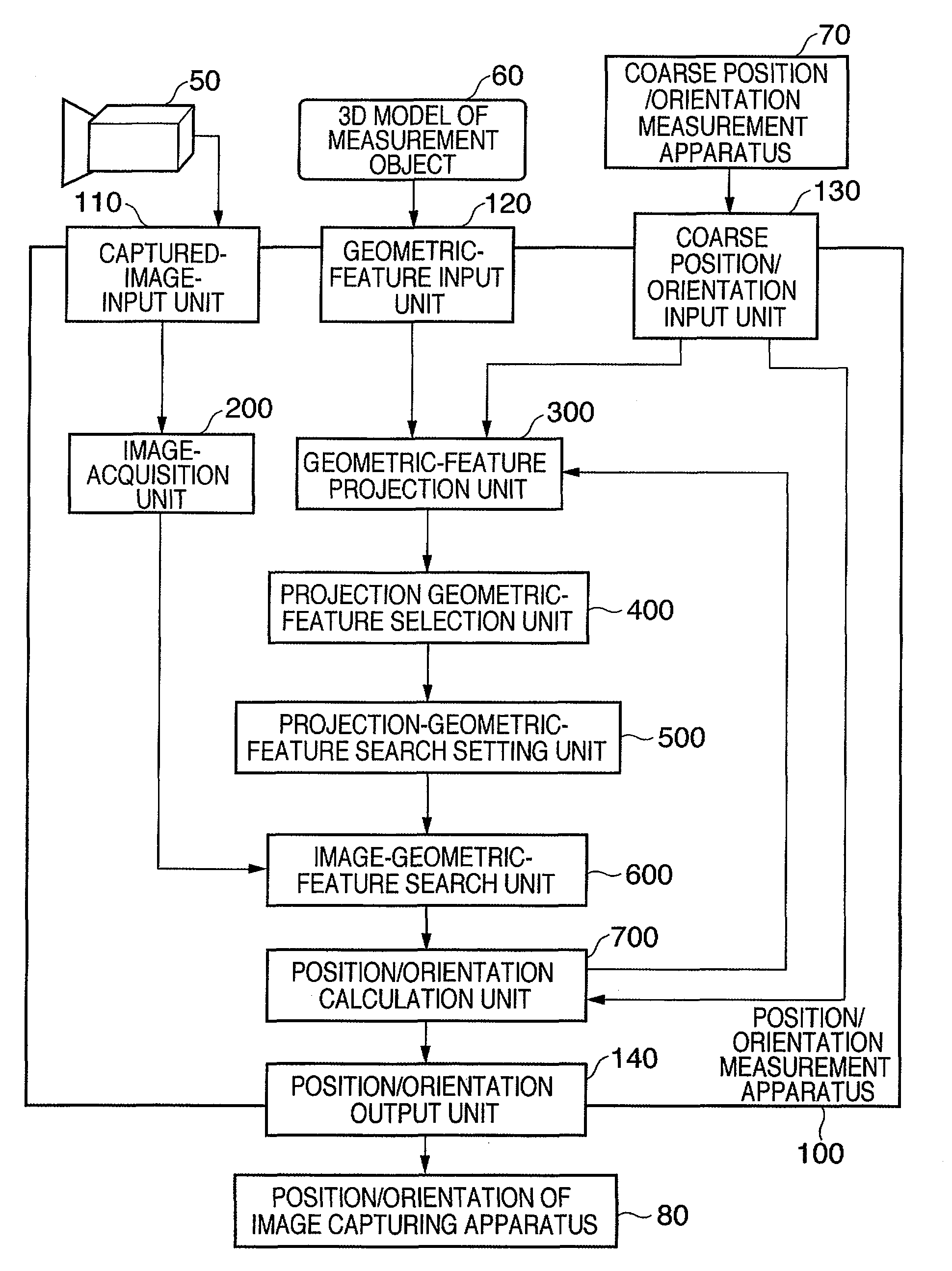
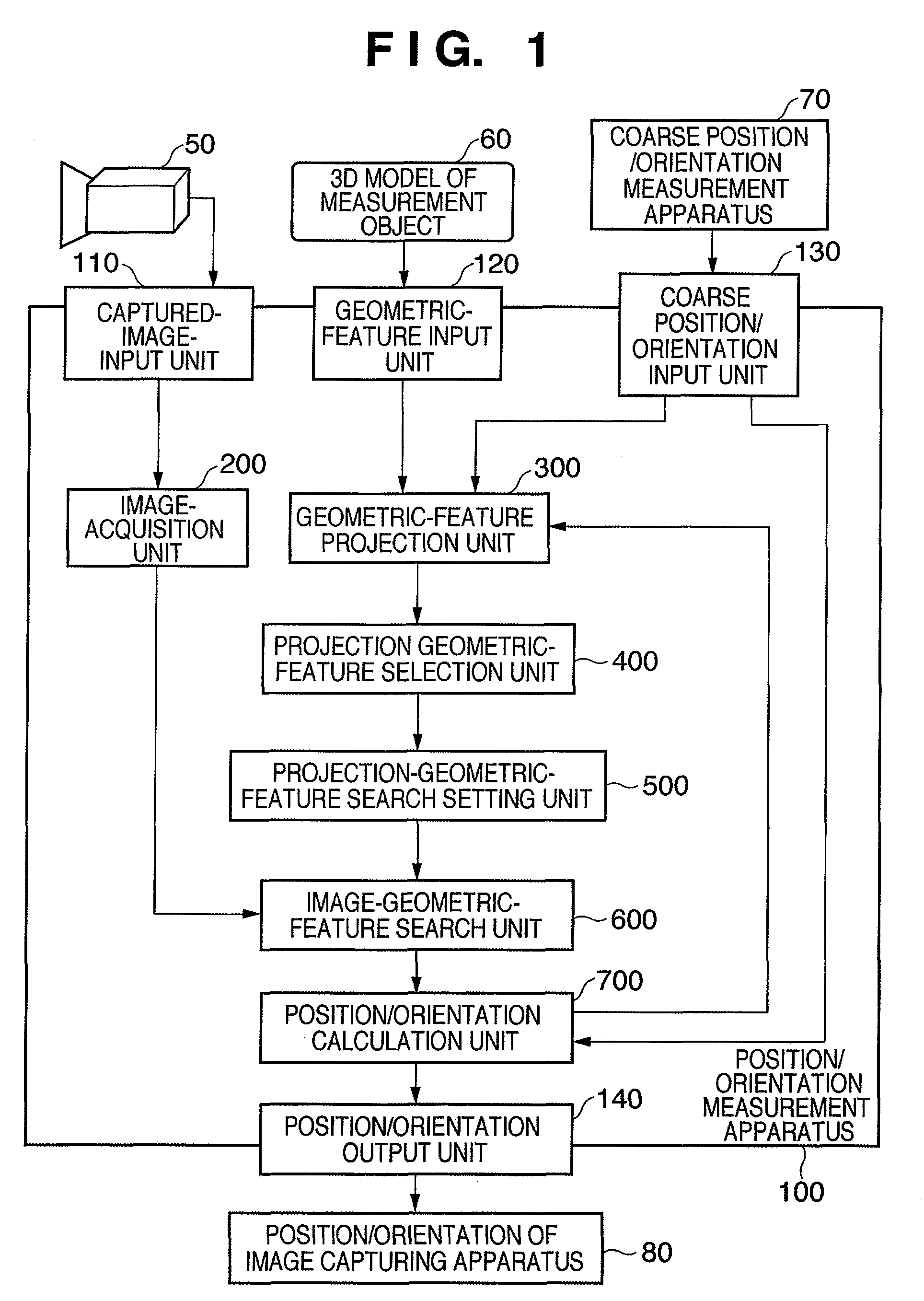
[0032]FIG. 1 is a block diagram showing a measurement apparatus 100 and an image-capturing apparatus 50. FIG. 1 illustrates the flow of processing and data flow in the measurement apparatus 100. It should be noted that the configuration of the measurement apparatus 100 shown below is partially or entirely implemented as a result of execution of a control program stored in a ROM or RAM, not shown, by a CPU, not shown. In other words, the measurement apparatus 100 may be implemented by executing a control program executing the hereinafter described processing on a regular computer.

[0033]In the measurement apparatus 100 of the present embodiment, an image-capturing apparatus 50, which captures images of a scene, and a coarse measurement apparatus 70 (marked “coarse position / orientation measurement apparatus” in the figures), which acquires the general position and orientation of the image-capturing apparatus 50, are connected via a captured-image-input unit 110 and a coarse input unit ...

embodiment 2

[0099]The above-described Embodiment 1 described a method, in which a search is carried out in a captured image for image geometric features corresponding to the positions of projection geometric features and position and orientation is estimated so as to decrease the distances therebetween. The ordinary Sobel operator and Canny operator can be uses in the detection of line segments carried out during the detection of image geometric features in captured images. Here, line segments detected by image processing in captured images (referred to as edges as appropriate) are called edge elements.

[0100]As far as the matching of projection geometric features and edge elements is concerned, assuming that a coarse position and orientation has been obtained, the edges possessing similar length, direction, etc. among edges located in the vicinity of the projection geometric features can be associated and position and orientation can be estimated so as to reduce the distances to these edge elem...

embodiment 3

[0101]When the measurement object is a 3D model having huge line segments, such as a model describing an entire building structure, the geometric features required for position and orientation estimation are subject to considerable variation depending on the distance between the image-capturing apparatus 50 and the measurement object. For this reason, if processing cannot be performed in an efficient manner, it becomes difficult to carry out position and orientation estimation within the imaging interval of the camera. In actual practice, in the captured image, the geometric features required for the estimation of position and orientation may possess a certain length and may have various directions.

[0102]Accordingly, processing that takes into consideration the sequence of processing of the geometric features required for position and orientation estimation makes it possible to process huge geometric features while maintaining the accuracy of position and orientation because the pro...


PUM


Abstract

A measurement apparatus (100), which measures the relative position and orientation of an image-capturing apparatus (50) capturing images of one or more measurement objects (10) with respect to the measurement object, acquires a captured image using the image-capturing apparatus (50). Moreover, the respective geometric features present in a 3D model of the measurement object (10) are projected onto the captured image based on the position and orientation of the image-capturing apparatus (50), thereby obtaining projection geometric features. Projection geometric features to be used in calculation of the position and orientation are then selected from the resultant projection geometric features based on distances between the projection geometric features in the captured image. The relative position and orientation of the image-capturing apparatus (50) with respect to the measurement object is then calculated using the selected projection geometric features and image geometric features corresponding to the selected projection geometric features detected in the captured image.

Description

BACKGROUND OF THE INVENTION[0001]1. Field of the Invention[0002]The present invention relates to a measurement apparatus and a control method, in which a model of a measurement object is used to measure the position and orientation of an image-capturing apparatus as the image-capturing apparatus captures an image of the measurement object.[0003]2. Description of the Related Art[0004]Measurement of the position and orientation of an image-capturing apparatus, such as a camera capturing an image of real space (hereafter referred to as a camera as appropriate), is required, for instance, in mixed reality systems providing a combined display of real space and virtual space.[0005]In the past, a method employing markers having known 3D positions was known as a method used for measuring the position and orientation of an image-capturing apparatus. In this method, the distance between the positions of markers detected in a captured image within the captured image and projected positions obt...

Claims


Application Information

Patent Timeline
Patent Type & Authority Patents(United States)
IPC IPC(8): G06K9/00
CPCG06T7/0028G06T7/0042G06K9/00201G01B11/14G06T2207/30244G06T7/33G06T7/73G06V20/64
Inventor KOBAYASHI, KAZUHIKOUCHIYAMA, SHINJI
Owner CANON KK
Why Eureka
Eureka Blog
Learn More