
Systems and methods for advanced card printing

a card printing and advanced technology, applied in the field of magnetic cards, can solve the problems of reducing the durability of the card, and so as to increase the whimsical and festive nature of the card, and without reducing the structural integrity of the card

Active Publication Date: 2012-12-04
DYNAMICS
View PDF240 Cites 80 Cited by
  • Summary
  • Abstract
  • Description
  • Claims
  • Application Information

AI Technical Summary

Benefits of technology

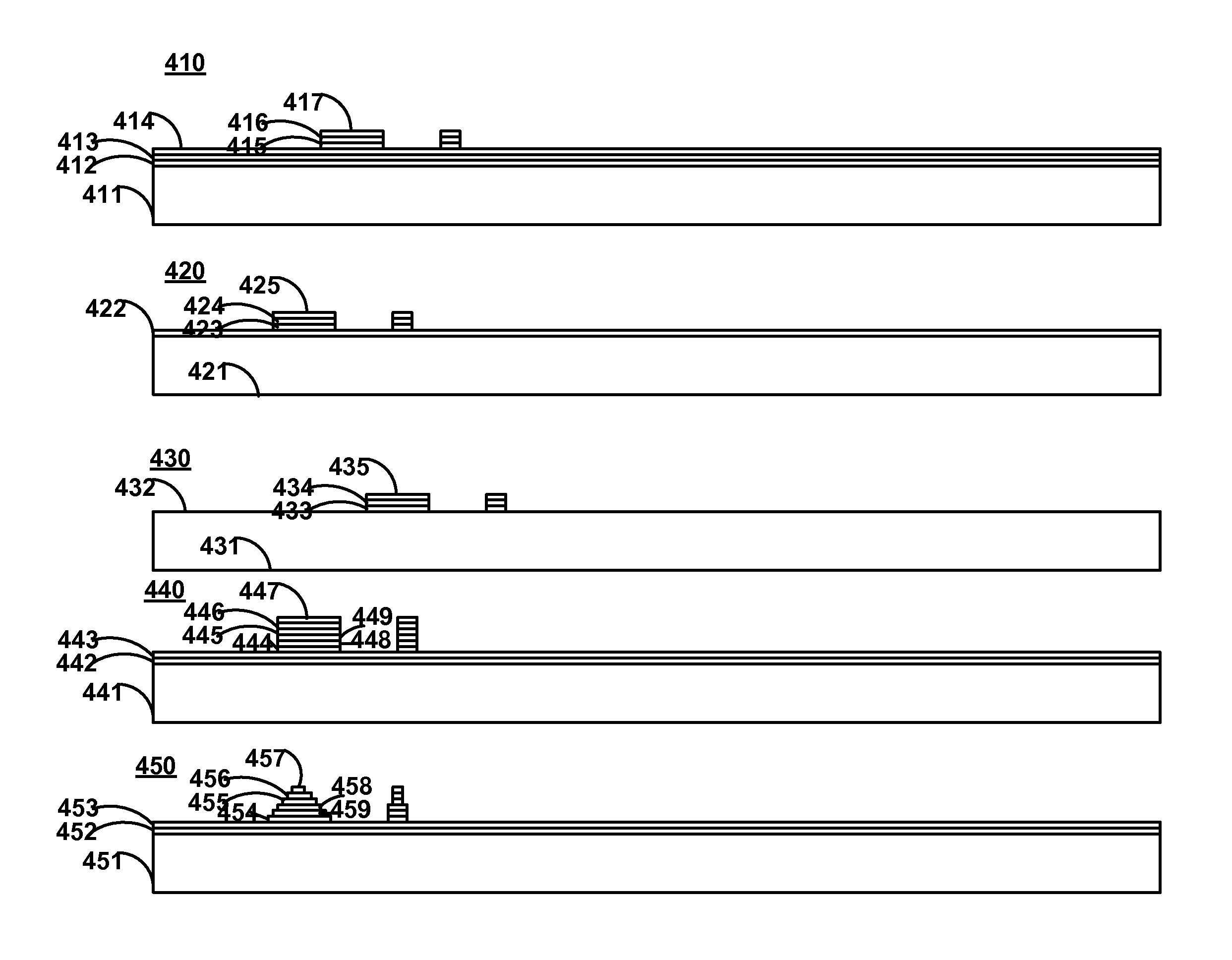
[0006]Systems and methods of card printing are provided that increase the whimsical and festive nature of a card without decreasing the structural integrity of the card. Particularly embossed and / or engraved indicia may be provided on the surface of a card without decreasing the structural integrity of the card.
[0008]All, or substantially all, of the front as well as the back of a card may be a display (e.g., bi-stable, non bi-stable, LCD, LED, or electrochromic display). Electrodes of a display may be coupled to one or more capacitive touch sensors such that a display may be provided as a touch-screen display. Any type of touch-screen display may be utilized. Such touch-screen displays may be operable of determining multiple points of touch. Accordingly, a barcode may be displayed across all, or substantially all, of a surface of a card. In doing so, computer vision equipment such as barcode readers may be less susceptible to errors in reading a displayed barcode.

Problems solved by technology

Such a traditional card embosser decreases the structural integrity of the card and, as such, reduces the durability of the card.
Such a traditional card engraver decreases the structural integrity of the card and, as such, reduces the durability of the card.

Method used


Image

  • Systems and methods for advanced card printing
  • Systems and methods for advanced card printing
  • Systems and methods for advanced card printing

Examples


Embodiment Construction

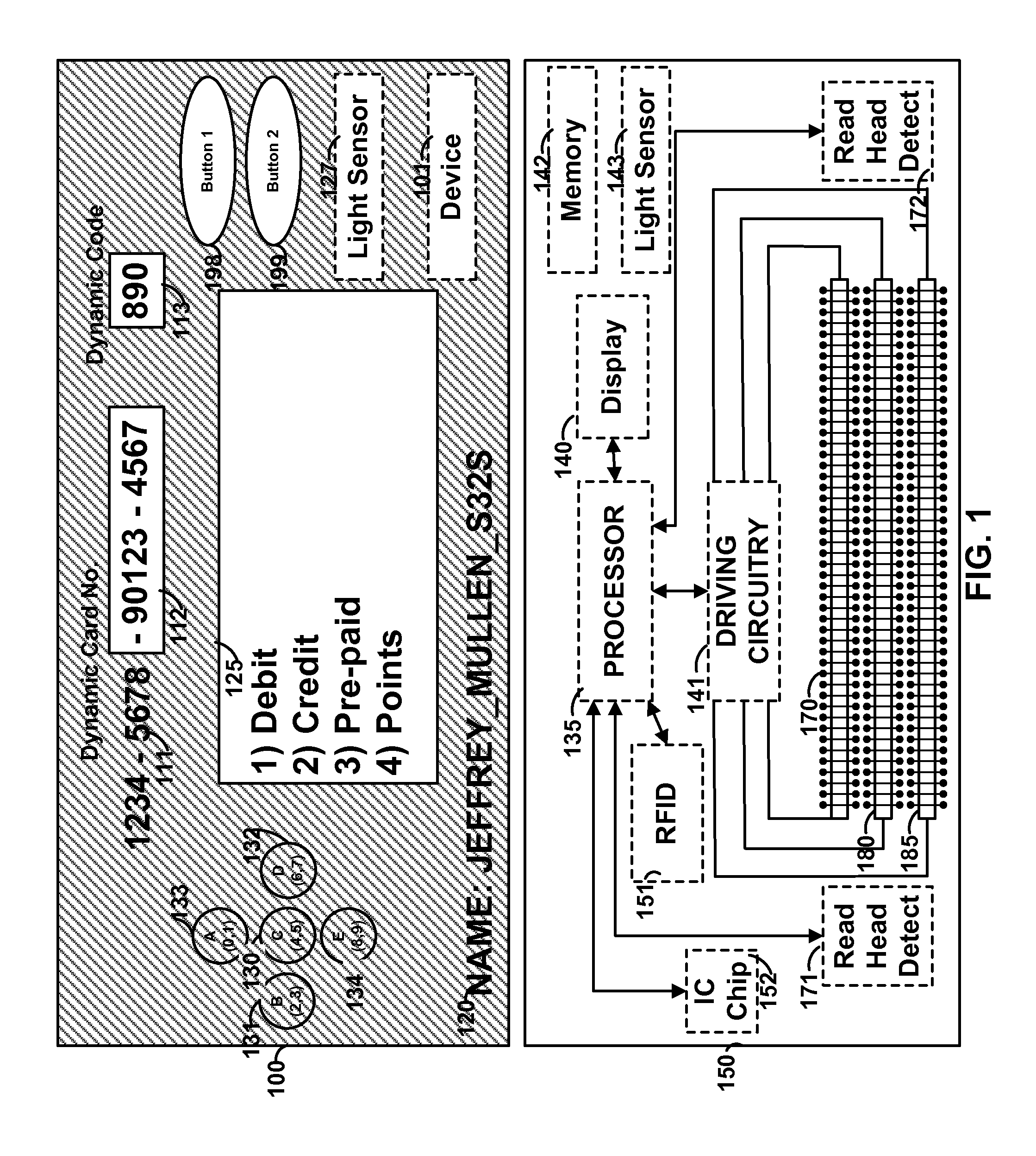
[0027]FIG. 1 shows card 100 that may include, for example, a dynamic number that may be entirely, or partially, displayed via display 112. A dynamic number may include a permanent portion such as, for example, permanent portion 111. Permanent portion 111 may be printed as well as embossed or laser etched on card 100. Multiple displays may be provided on a card. For example, display 113 may be utilized to display a dynamic code such as a dynamic security code. Display 125 may also be provided to display logos, barcodes, as well as multiple lines of information. A display may be a bi-stable display or non bi-stable display. Permanent information 120 may also be included and may include information such as information specific to a user (e.g., a user's name or username) or information specific to a card (e.g., a card issue date and / or a card expiration date). Card 100 may include one or more buttons such as buttons 130-134. Such buttons may be mechanical buttons, capacitive buttons, or...


PUM

PropertyMeasurementUnit
Thicknessaaaaaaaaaa
Coloraaaaaaaaaa
Widthaaaaaaaaaa

Abstract

Layers of colored polymers are applied to a surface of a card and are hardened and adhered to a card via light such as ultraviolet or light having a wavelength in the blue spectrum. The layers may be applied to form three dimensional indicia on the surface of the card. For example, letters, numbers, logos, and other indicia (e.g., pictures) may be printed three dimensionally onto the surface of the card. Troughs may be formed via such layering such that indicia is provided as indentations into the added layers. Extensions may be formed via such layering such that indicia is provided as extensions from the added layers. Indicia may be provided via extensions and / or indentations. As such, embossed and / or engraved indicia may be provided on the surface of a card without impacting the structural integrity of the card.

Description

CROSS-REFERENCE TO RELATED APPLICATION[0001]This application claims the benefit of U.S. Provisional Patent Application No. 61 / 367,598, titled “SYSTEMS AND METHODS FOR ADVANCED CARD PRINTING,” filed Jul. 26, 2010, which is hereby incorporated by reference herein in its entirety.BACKGROUND OF THE INVENTION[0002]This invention relates to magnetic cards and devices and associated payment systems.[0003]A traditional card embosser physically punches a payment card number partially through one surface of a card such that the payment card number extends from the other surface of the card. Such a traditional card embosser decreases the structural integrity of the card and, as such, reduces the durability of the card.[0004]A traditional card engraver physically engraves a payment card number partially through one surface of a card. Such a traditional card engraver decreases the structural integrity of the card and, as such, reduces the durability of the card.[0005]It is therefore desirable to...

Claims


Application Information

Patent Timeline
IPC IPC(8): G06K19/02
CPCG06K19/06206G06K19/07707G06K19/07722G06K19/07749B32B37/185B32B2309/105B32B2327/06B32B2425/00B32B2457/20B32B2519/02G06K19/02
Inventor MULLEN, JEFFREY D.NICKLAUS, ERIC R.
Owner DYNAMICS
Learn More