
Combined power transmission, drive unit and drive train for a hybrid system

a hybrid system and drive unit technology, applied in the direction of mechanical equipment, couplings, transportation and packaging, etc., can solve the problems of unintentional closure and drive response, and achieve the effect of reducing hydrodynamic influences and improving the selection behavior of the selectable clutch devi

Active Publication Date: 2012-12-04
SCHAEFFLER TECH AG & CO KG
View PDF14 Cites 17 Cited by
  • Summary
  • Abstract
  • Description
  • Claims
  • Application Information

AI Technical Summary

Benefits of technology

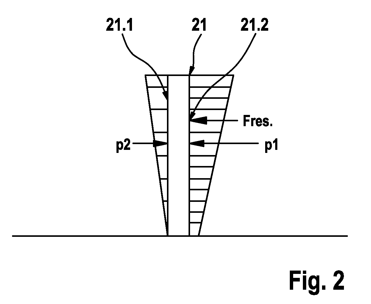
The invention is about improving a combined power transmission and drive unit for hybrid systems with at least two prime movers. The invention focuses on improving the selection behavior of the selectable clutch device and reducing the impact of hydrodynamic influences on the selectable clutch device. The solution involves controlling the rotary velocity difference of the flow medium on both sides of the piston element of the servo unit, which can be achieved by using an axial bearing between the controlling element and a connection element. This allows for effective shielding of the piston element from axial forces and reduces the need for additional modifications to the control of clutch actuation. The invention is applicable to a wide range of drive trains and can be easily integrated into existing systems.

Problems solved by technology

In the inconvenient case, this can lead to unintentional closure of the selectable clutch device and cause disadvantageous effects on drive responses, which, in particular, are characteristic of undesired dragging of connected elements coupled with the first clutch part.

Method used


Image

  • Combined power transmission, drive unit and drive train for a hybrid system
  • Combined power transmission, drive unit and drive train for a hybrid system
  • Combined power transmission, drive unit and drive train for a hybrid system

Examples


Embodiment Construction

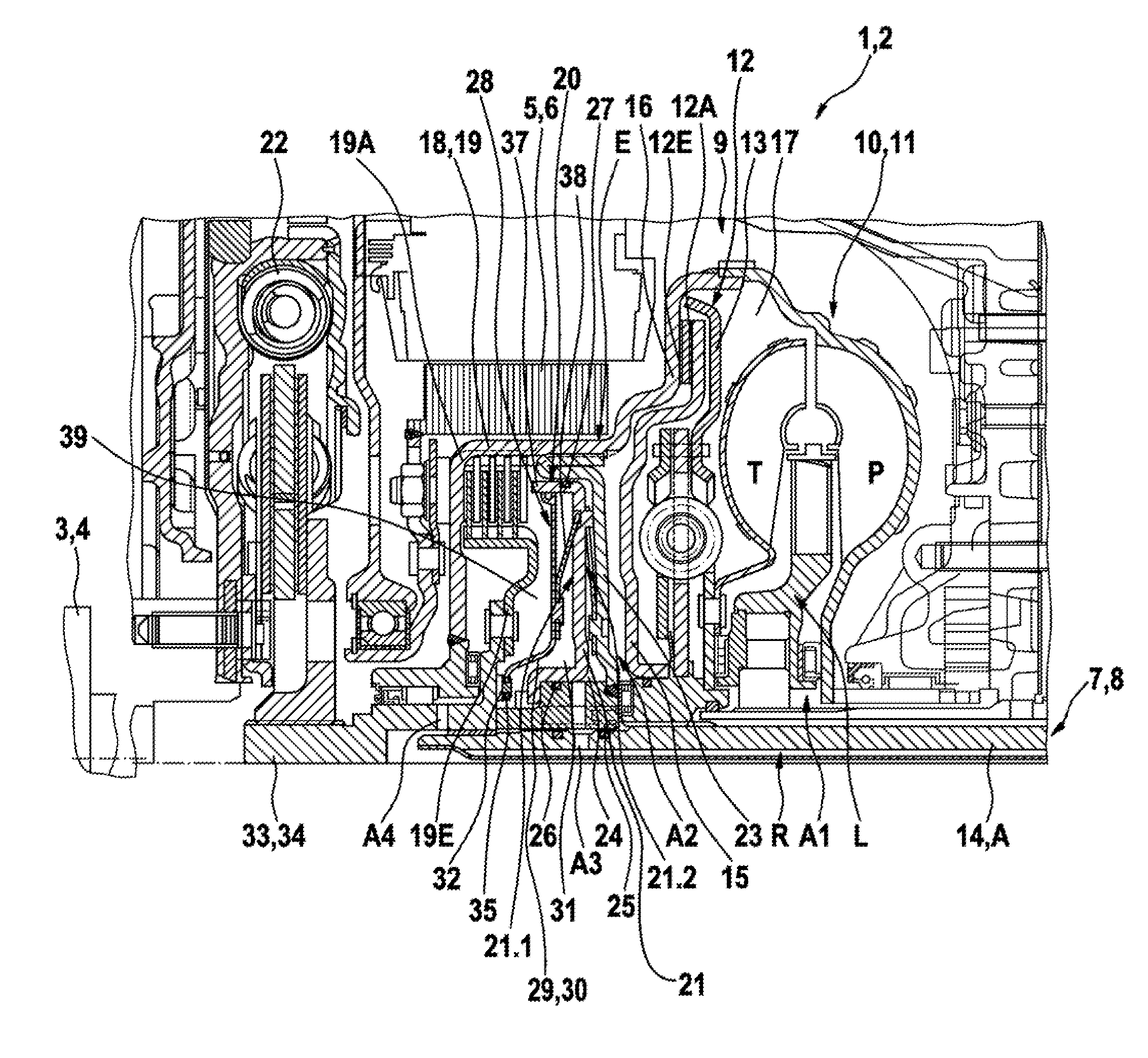
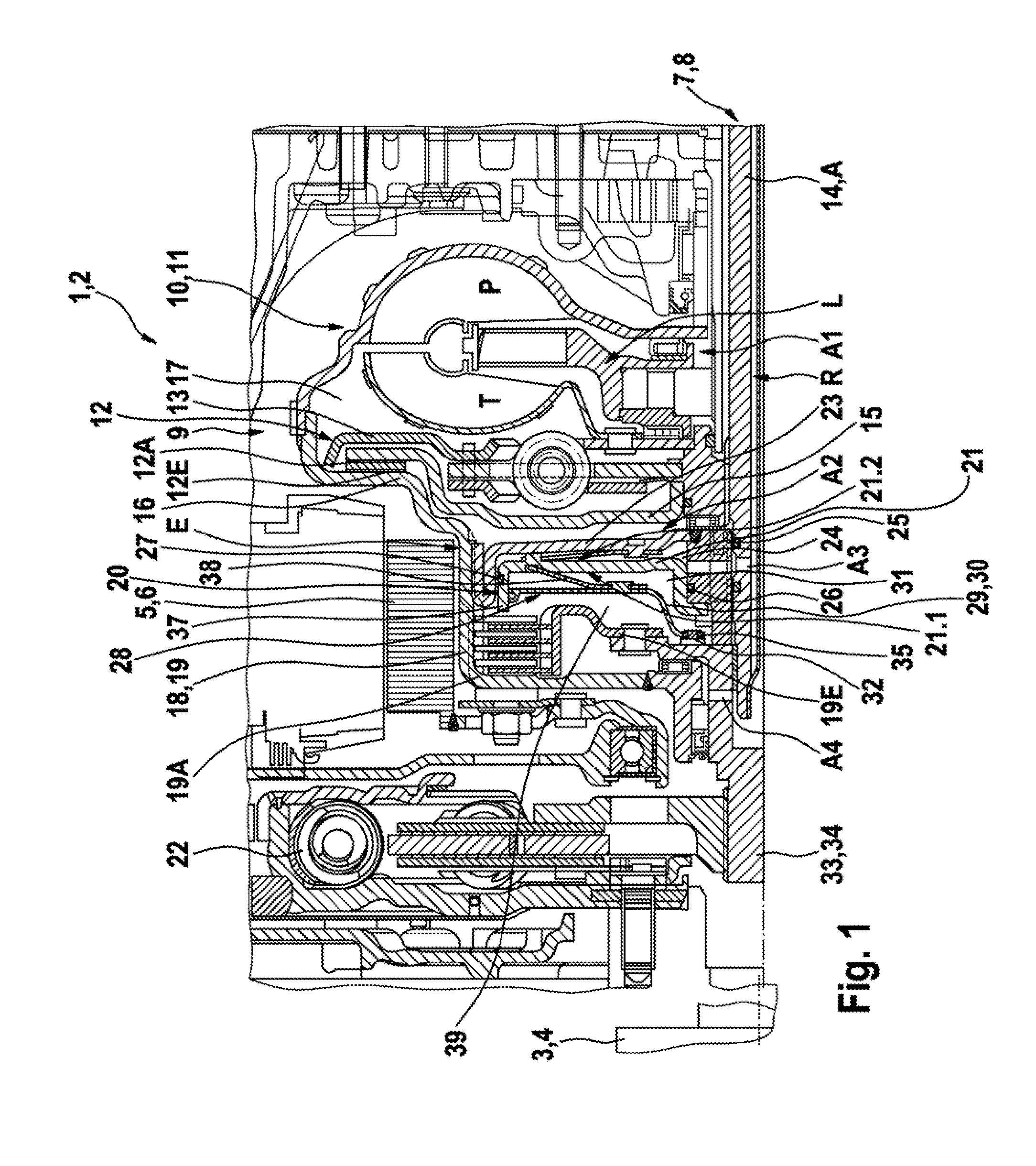
[0024]FIG. 1 is a schematically simplified illustration of basic design and function of an embodiment of a combined power transmission and drive unit 1 according to the invention, as it can find application in drive trains for hybrid systems 2. Unit 1 is disposed between a first prime mover 3, for example, in the form of an internal combustion engine 4 and a downstream transmission 8 as a consumer 7. Furthermore, a further second prime mover 5 is provided, for example, in the form of an electric machine 6 that can be operated as generator and as motor.

[0025]The individual prime movers 3 and 5 are coupled with the transmission 8 via a power transmission unit 9, including at least one hydrodynamic component 10 that in the depicted case is, for example, provided as a hydrodynamic rotation speed / torque converter 11. This serves for concurrent conversion of rotation speed and torque in a predefined ratio. The hydrodynamic rotation speed / torque converter 11 comprises at least a primary wh...


PUM


Abstract

A combined power transmission and drive unit for the application in drive trains in hybrid systems with at least two prime movers that can be coupled via a power transmission unit with a consumer, in particular transmission. Between a first prime mover and the power transmission unit, a device is provided for connecting / disconnecting the power flow between the latter and the power transmission unit, including a friction clutch that can be actuated by a pressure medium, including a first clutch part and a second clutch part which can be brought in active connection with one another via a servo unit featuring a piston element that can be pressurized by a pressure medium. A combined power transmission and drive unit according to the invention, with control of a rotation speed difference of a flow medium on either face side of a piston element.

Description

CROSS-REFERENCE TO RELATED APPLICATIONS[0001]This patent claims priority of German Patent Application No. 10 2008 037 804.6, filed on Aug. 14, 2008, which application is incorporated herein by reference.FIELD OF THE INVENTION[0002]The invention relates to a combined power transmission and drive unit for application in drive trains in hybrid systems with at least two prime movers that can be coupled with a consumer via a power transmission unit, in particular a transmission. Between a first prime mover and the power transmission unit a mechanism is provided for connecting / disconnecting the power flow between the latter and the power transmission unit. The mechanism includes a friction clutch with a first clutch part and a second clutch part, which can be brought in active connection with one another via a servo unit featuring a piston element that can be activated with pressure medium.[0003]The invention further relates to a drive train for a hybrid system, in particular for applicat...

Claims


Application Information

Patent Timeline
Patent Type & Authority Patents(United States)
IPC IPC(8): F16D25/0638B60K6/387
CPCF16D25/0638F16D2048/0212
Inventor MUELLER, BRUNOKRAUSE, THORSTEN
Owner SCHAEFFLER TECH AG & CO KG
Learn More