
Wind power generator

a wind power generator and wind power technology, applied in the direction of electric generator control, machines/engines, final product manufacturing, etc., can solve the problems of difficult to move the crane, many limitations of carriage and installation of large-sized cranes, and the gradual growth of wind power generators. , to achieve the effect of improving operation rate and power generation efficiency, easy and safe repair, and easy and quick completion

Active Publication Date: 2012-11-27
DMS CO LTD
View PDF9 Cites 7 Cited by
  • Summary
  • Abstract
  • Description
  • Claims
  • Application Information

AI Technical Summary

Benefits of technology

The present invention provides a wind power generator that is easy to maintain, safe, and cost-effective without the need for a large-sized crane. The generator is designed to improve operation and power generation efficiency by reducing repairing time. It is also environmentally friendly by minimizing forest damage during installation. The wind power generator includes a pillar, a nacelle platform, a service crane, a generator assembly, a rotor hub, and a plurality of blades. The rotor hub is provided with pulleys for guiding a cable and the generator assembly includes guides for supporting the cable. The wind power generator can be easily and safely repaired without damaging the forests even when installed at a mountainous area. It is also eco-friendly as it does not require a large-sized crane for installation or repairing.

Problems solved by technology

Wind power generators are gradually becoming large-sized, and thus a large-sized hydro-crane of more than 100 tons is required to install large-sized wind power generators.
The large-sized crane has many limitations in carriage and installation.
That is, since the crane used for installing the wind power generator is large-sized, when road conditions are not good it is difficult to move the crane.
Particularly, when the large-sized crane moves along mountainous areas, forests are damaged in the course of making a pathway for the crane.
The time and costs for recovering the forests are large.
In addition, when the installed wind power generator fatally breaks down, there is a need to repair the wind power generator after disassemble thereof.
At this point, since the large-sized crane should be transported through the mountainous area, the time and costs are additional incurred.
Accordingly, the operational efficiency of the wind power generator is deteriorated.

Method used


Image

  • Wind power generator
  • Wind power generator
  • Wind power generator

Examples


Embodiment Construction

[0039]Hereinafter, referring to the drawings, the present invention will be described with reference to exemplary embodiments.

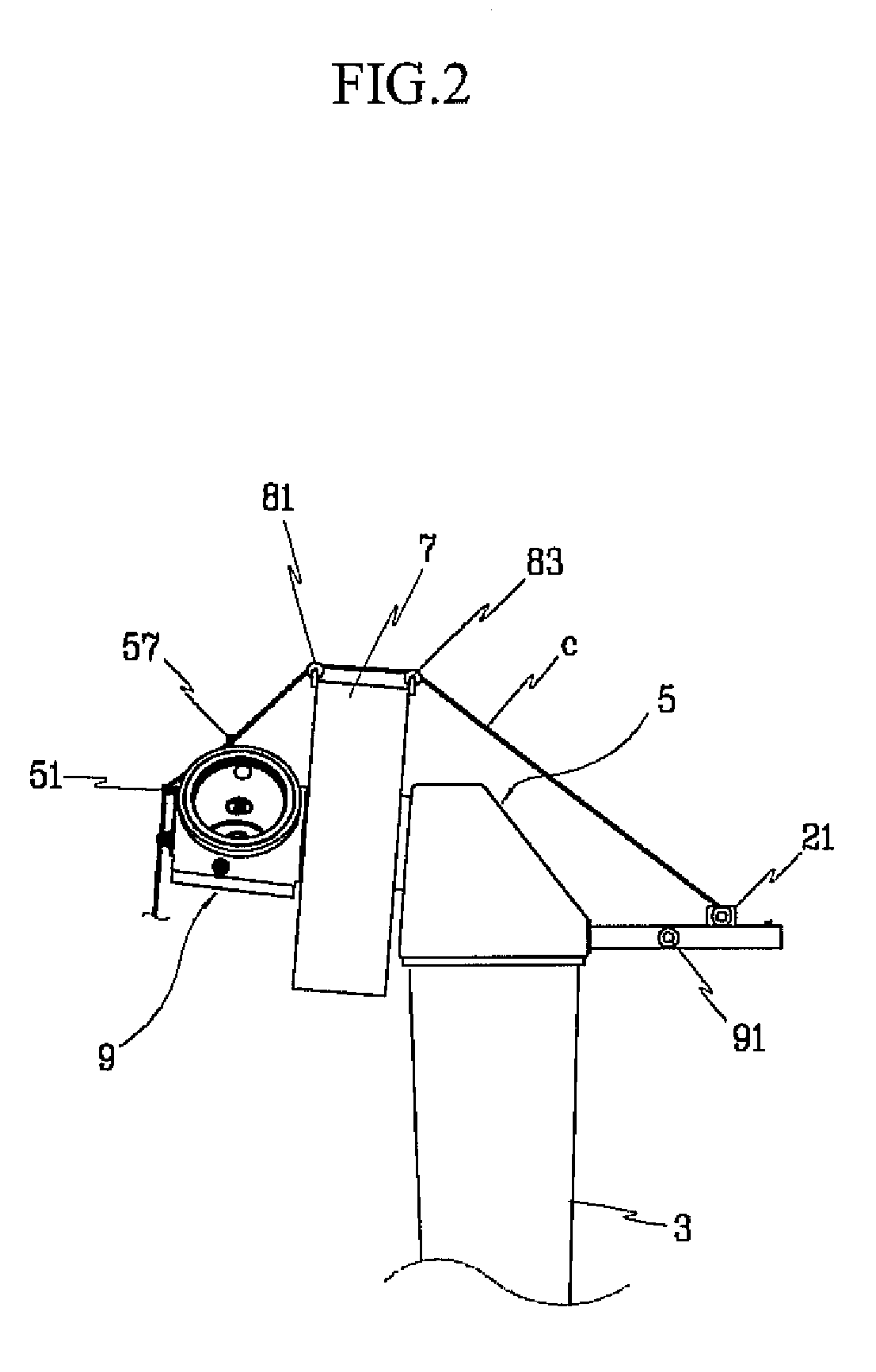
[0040]FIG. 1 is a schematic view of a wind power generator according to an exemplary embodiment of the present invention. Referring to FIG. 1, a wind power generator includes a base 1 installed on the ground, a pillar 3 fixedly erected on the base 1, a nacelle platform 5 disposed on the pillar 3, a generator assembly 7 coupled to the nacelle platform 5, a rotor hub 9 coupled to the generator assembly 7, and a plurality of blades 11, 13, and 15 coupled to the rotor hub 9.

[0041]The base 1 is formed by casting concrete on the ground to securely fix the pillar 3. The pillar 3 generally exceeds tens of meters in height. The pillar 3 may be formed of concrete or metal.

[0042]The nacelle platform 5 is installed at an upper end portion of the pillar 3. Components required for power generation are disposed in the nacelle platform 5. As shown in FIG. 2, the nacelle plat...


PUM


Abstract

A wind power generator includes a pillar fixed on a base, a nacelle platform disposed on an upper end portion of the pillar, a service crane provided at a side of the nacelle platform, a generator assembly coupled to the nacelle platform, a rotor hub rotatably coupled to the generator assembly, and a plurality of blades coupled to the rotor hub and rotating the rotor hub. The rotor hub is provided at an outer circumference of a front end thereof with a plurality of first pulleys for guiding a case from a winch installed on the ground.

Description

CROSS-REFERENCE TO RELATED APPLICATION[0001]This application claims priority to and the benefit of Korean Patent Application No. 10-2009-0028984 filed in the Korean Intellectual Property Office on Apr. 3, 2009, the entire contents of which are incorporated herein by reference.BACKGROUND OF THE INVENTION[0002](a) Field of the Invention[0003]The present invention relates to a wind power generator. More particularly, the present invention relates to a wind power generator that is designed in a large size and can be easily installed while providing convenient maintenance.[0004](b) Description of the Related Art[0005]Generally, a wind power generator is installed at a mountainous area and the seaside considering characteristics of wind resources. Wind power generators are gradually becoming large-sized, and thus a large-sized hydro-crane of more than 100 tons is required to install large-sized wind power generators.[0006]The large-sized crane has many limitations in carriage and installa...

Claims


Application Information

Patent Timeline
Patent Type & Authority Patents(United States)
IPC IPC(8): F03D9/00H02P9/04
CPCF03D1/001F05B2230/61F05B2230/80Y02P70/523Y02E10/725Y02E10/726Y02E10/728F05B2240/916F03D13/10Y02E10/72Y02P70/50F03D80/00
Inventor SONG, SUNG-HOCHOI, MAN-SOOLIM, PIL-JOO
Owner DMS CO LTD
Learn More