
Modular hydraulic thruster system for vessel

a module-type, hydraulic thruster technology, applied in the direction of special-purpose vessels, motor-driven power plants, vessel construction, etc., can solve the problems of lack of readily available instruments, lack of quick and easy means to add additional thrusters to the system, etc., to achieve precise operation of the vessel, increase safety, and improve the effect of vessel operation

Active Publication Date: 2012-11-27
WILLIAMS JOHN T
View PDF22 Cites 4 Cited by
  • Summary
  • Abstract
  • Description
  • Claims
  • Application Information

AI Technical Summary

Benefits of technology

[0009]Accordingly, it is an object of the present invention to provide a modular hydraulic thruster system for vessel which provides thrust angle information to the pilot. Design features allowing this object to be accomplished include thrust angle detection means to detect a thrust angle of the propeller electrically connected to a thruster angle indicator in an instrument panel. Advantages associated with the accomplishment of this object include increased safety and efficiency of operation.
[0010]It is another object of the present invention to provide a modular hydraulic thruster system for vessel which advises the open / closed status of thruster tube gear clamp(s). Design features allowing this object to be accomplished include tube gear clamp OPEN / CLOSED status indication means electrically connected to a tube gear clamp status indicator in an instrument panel. Benefits associated with the accomplishment of this object include greater facility of operation and aid in eliminating errors when extending and retracting the thruster tube.
[0011]It is still another object of this invention to provide a modular hydraulic thruster system for vessel which provides effective protection to tube gear clamp hydraulic lines and tube gear clamp wire. Design features enabling the accomplishment of this object include a swivel union whose swivel union rotating section is attached to a tube, and whose swivel union stationary section is prevented from rotating relative to a thruster housing, and flexible spiral conduit slidably encircling the tube from the swivel union to the tube gear clamp. Advantages associated with the realization of this object include the ability to protect tube gear clamp hydraulic and electrical lines, while extending and retracting the tube relative to the housing.

Problems solved by technology

A number of designs exist for this type of flat boat propulsion system, with attendant problems.
One problem is the lack of readily available instrumentation to depict important condition information such as the angle of thrust at which a given thruster is aiming relative to the centerline of the vessel to which it is attached, the power output being developed in terms of propeller revolutions per minute, the tilt angle of the thruster lower unit, the degree of extension or retraction of the thruster lower unit, and the condition of any clamps in the system (open or closed).
Another problem with existing marine thruster designs is the absence of a quick and easy means to add additional thrusters to the system, as required.

Method used


Image

  • Modular hydraulic thruster system for vessel
  • Modular hydraulic thruster system for vessel
  • Modular hydraulic thruster system for vessel

Examples


Embodiment Construction

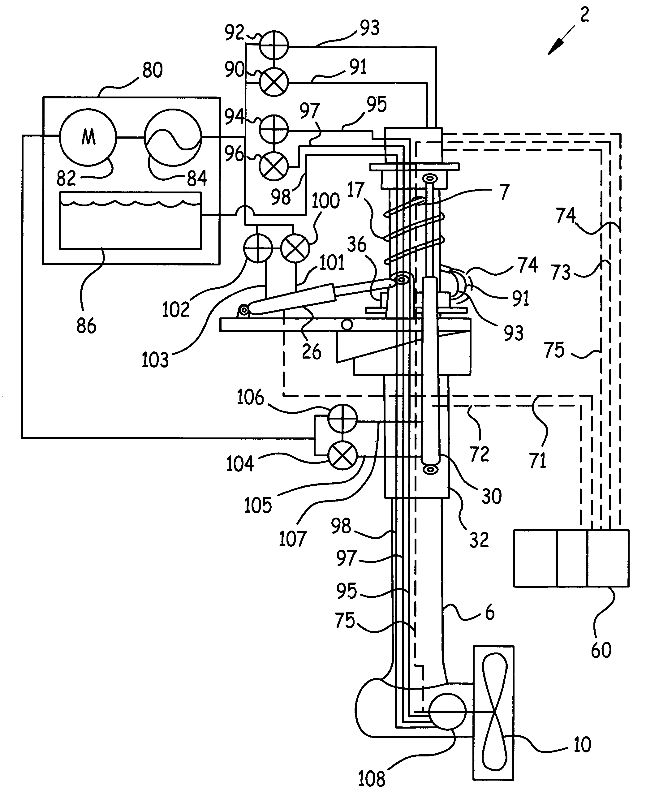
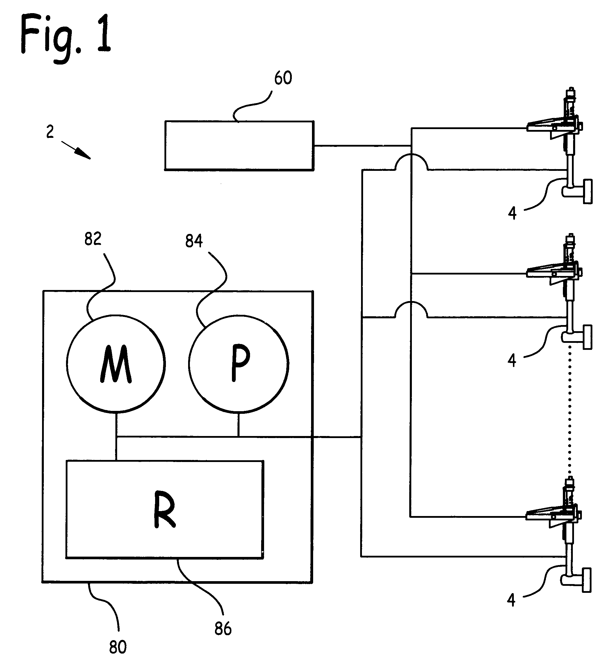
[0025]FIG. 1 is a schematic diagram of the instant modular hydraulic thruster system for vessel 2. Referring to this figure, modular hydraulic thruster system for vessel 2 comprises power pack 80, instrument panel 60, and at least one thruster 4 electrically and / or hydraulically connected to instrument panel 60 and power pack 80. As may be observed in FIG. 1, any number of thrusters 4 may be connected to instrument panel 60 and power pack 80, depending on the needs of the individual vessel upon which modular hydraulic thruster system for vessel 2 is installed.

[0026]Power pack 80 comprises prime mover 82, pump 84, and reservoir 86. In the preferred embodiment, prime mover 82 was a diesel or internal combustion engine, pump 84 was a hydraulic pump driven by prime mover 82, and reservoir 86 contained hydraulic fluid pumped by pump 84, as driven by prime mover 82.

[0027]Instrument panel 60 contains instrumentation to continuously communicate information and status including displays of t...


PUM


Abstract

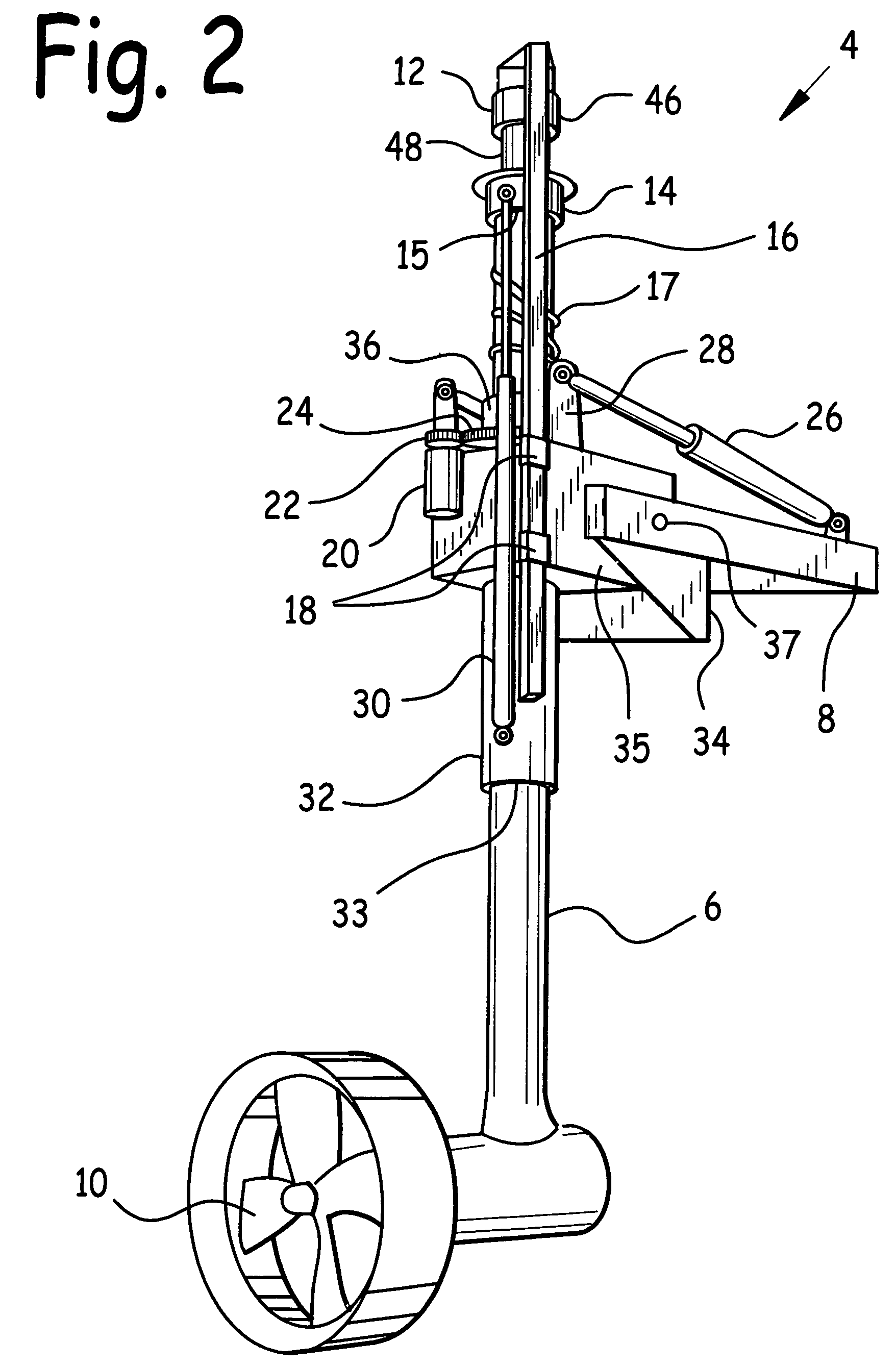
A modular hydraulic thruster system for vessel. At least one thruster is hydraulically connected to a power pack and electrically connected to an instrument panel. The instrument panel has a thrust angle indicator, tube gear clamp status indicator, extension indicator, tilt angle indicator, and tachometer, all pertaining to each thruster. The thruster includes a tube rotating and reciprocating through a housing, which is rotatably attached to a bracket. A swivel union is attached to one end of the tube; a hydraulic motor drives a propeller to an opposite end of the tube. Some instrumentation electrical and hydraulic lines are routed through the swivel union and into the tube; others are further routed out of the tube through a tube aperture and through a flexible spiral conduit to accommodate tube reciprocation within the housing. Means is disclosed to prevent a swivel union stationary section from rotating relative to the housing.

Description

CLAIM FOR PRIORITY[0001]This utility patent application is a Continuation-In-Part of U.S. application Ser. No. 12 / 381,245 filed Mar. 10, 2009 entitled now U.S. Pat. No. 7,883,384 Self-Contained Hydraulic Thruster for Vessel, which is a Continuation-In-Part of U.S. application Ser. No. 11 / 999,531 filed Dec. 6, 2007 now U.S. Pat. No. 7,654,875 entitled Self-Contained Hydraulic Thruster for Vessel, which was based upon U.S. provisional patent application Ser. No. 60 / 903,400 filed Feb. 26, 2007 entitled Modular Hydraulic Thruster System for Vessel; and claims the benefit of the earlier filing date of these applications.BACKGROUND OF THE INVENTION[0002]1. Field of the Invention[0003]This invention relates to vessel propulsion systems, and in particular to a modular hydraulic thruster system for vessel.[0004]2. Background of the Invention[0005]Marine thrusters typically mount on barges and flat boats, and are used as propulsion for these vessels. One type of marine thruster employs a prim...

Claims


Application Information

Patent Timeline
Patent Type & Authority Patents(United States)
IPC IPC(8): B63H21/12
CPCB63H21/165
Inventor WILLIAMS, JOHN T.
Owner WILLIAMS JOHN T
Learn More