
Compound-arm manipulator

a manipulator and compound arm technology, applied in the direction of lifting devices, curtain suspension devices, manual control with multiple control members, etc., can solve the problems of difficult task of fitting the object being carried into a fixture, reducing the footprint of the linkage, and reducing the range of motion

Active Publication Date: 2012-11-27
GIVENS RAY
View PDF59 Cites 19 Cited by
  • Summary
  • Abstract
  • Description
  • Claims
  • Application Information

AI Technical Summary

Benefits of technology

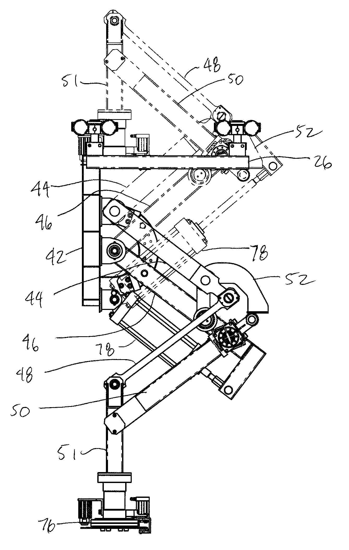
[0004]In one aspect, the invention is directed to a manipulator that is relatively compact and has a relatively large range of motion. The manipulator includes a linkage that folds back on itself. This reduces the footprint of the linkage. In a particular embodiment, the manipulator includes a linkage and a load balancing device. The linkage includes a first link, a second link, a third link and a fourth link. The first link and second links are rotatably connected to a base about first and second connection axes. The third and fourth links are connected to the first and second links respectively about third and fourth connection axes respectively. The third and fourth links are rotatably connected to a lift arm about fifth and sixth connection axes respectively, wherein the fifth and sixth connection axes are horizontally displaced from the third and fourth connection axes in the direction of the first and second connection axes. The load balancing device is configured to support the linkage in a selected position against a load and configured to permit the load to be moved upwards or downwards with a selected amount of force on the lift arm.

Problems solved by technology

A significant disadvantage, however with a typical overhead crane is that the operator receives no tactile feedback from the hoist.
As a result, the task of fitting the object being carried into a fixture or placing a heavy object lightly in contact with another object is relatively difficult.

Method used


Image

  • Compound-arm manipulator
  • Compound-arm manipulator
  • Compound-arm manipulator

Examples


Embodiment Construction

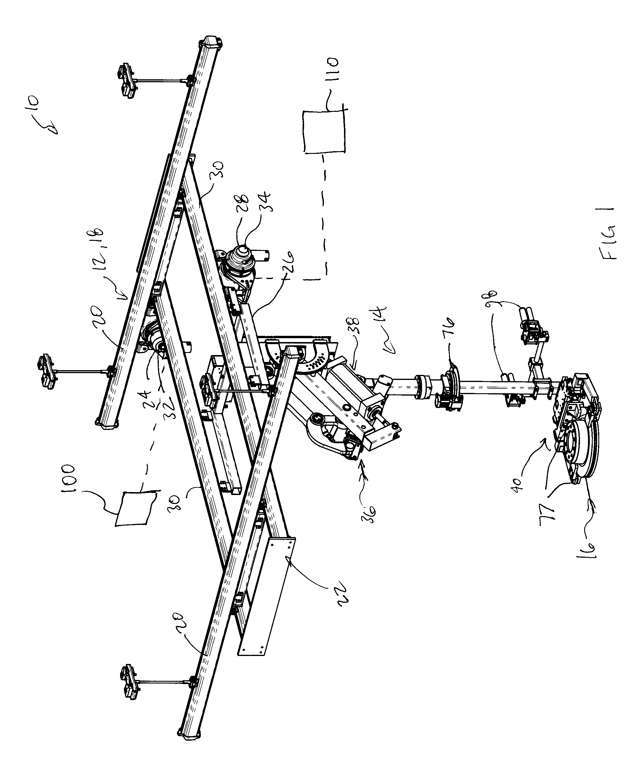
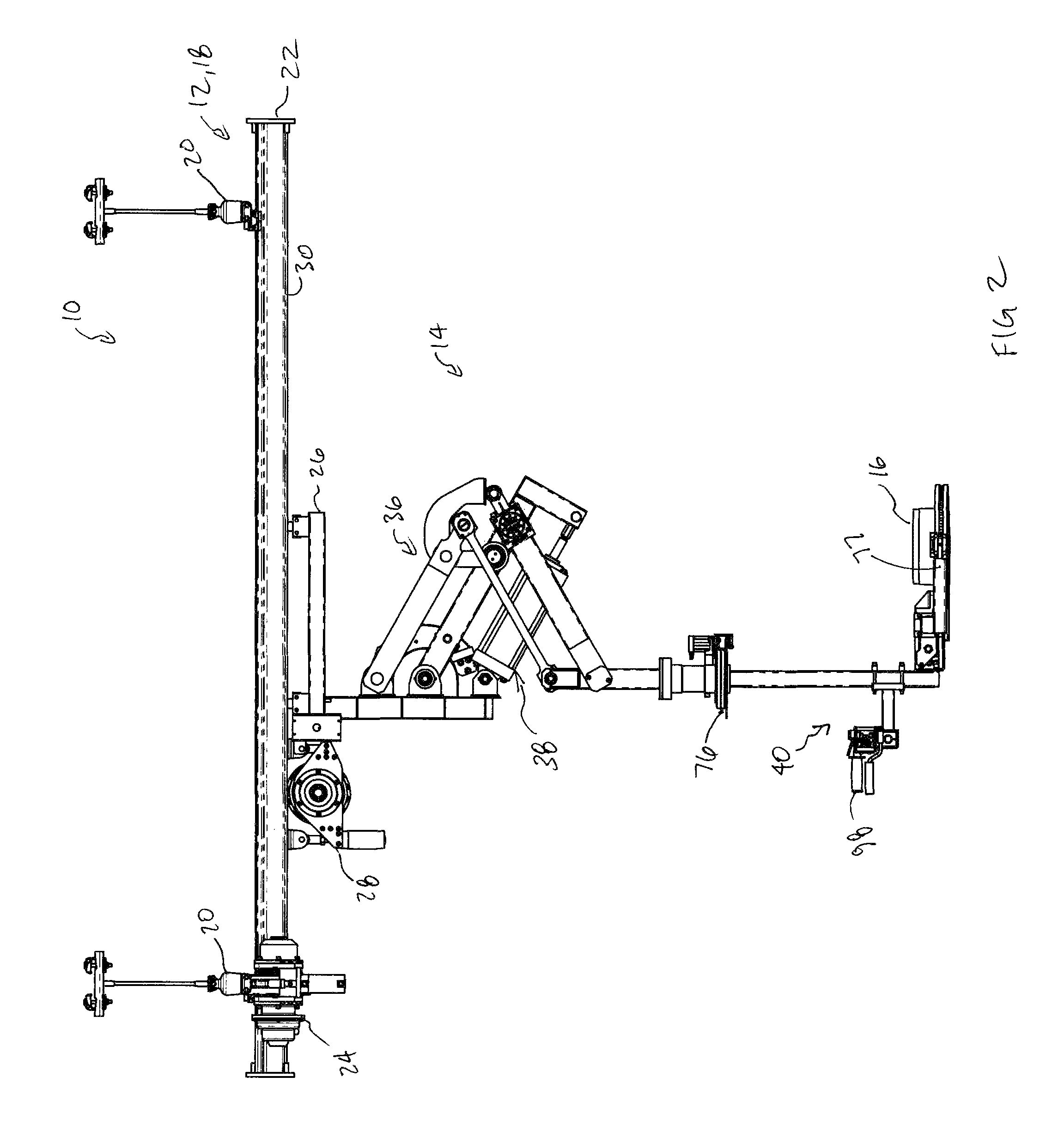
[0012]Reference is made to FIG. 1, which shows a load maneuvering system 10 for moving a load, in accordance with an embodiment of the present invention. The load maneuvering system 10 includes a transport system 12 and a manipulator 14.

[0013]The transport system 12 may be configured to support horizontal movement of the manipulator 14, and the manipulator 14 may be configured to support vertical movement of an object 16, which may also be referred to as a load 16.

[0014]The transport system 12 may be any suitable type of transport system, such as an overhead crane system 18. The overhead crane system 18 may include a pair of runway rails 20, a bridge 22, a bridge drive system 24, a carriage 26 and a carriage drive system 28.

[0015]The runway rails 20 together make up the runway and are fixable to any suitable location such as the ceiling of an industrial facility. The bridge 22 rides on and spans the runway rails 20 and is movable in a first horizontal direction. The bridge 22 includ...


PUM


Abstract

In a first aspect, the invention is directed to a manipulator that is relatively compact and has a relatively large range of motion. The manipulator includes a linkage that folds back on itself, which reduces the footprint of the linkage. In a particular embodiment, the manipulator includes a linkage and a load balancing device. The linkage includes a first link, a second link, a third link and a fourth link. The first link and second links are rotatably connected to a base about first and second connection axes. The third and fourth links are connected to the first and second links respectively about third and fourth connection axes respectively. The third and fourth links are rotatably connected to a lift arm about fifth and sixth connection axes respectively, wherein the fifth and sixth connection axes are horizontally displaced from the third and fourth connection axes in the direction of the first and second connection axes. The load balancing device is configured to support the linkage in a selected position against a load and configured to permit the load to be moved upwards or downwards with a selected amount of force on the lift arm. The manipulator may be provided as part of a load maneuvering system that further includes a transport system that may be similar to that used on an overhead crane.

Description

FIELD OF THE INVENTION[0001]The present invention relates to load maneuvering systems, and more particularly to a load maneuvering system that incorporates a manipulator.BACKGROUND OF THE INVENTION[0002]An overhead crane typically includes a pair of runway rails, a bridge that runs on the runway rails, a carriage that runs on rails on the bridge and a chain hoist or some similar structure that is connected to the carriage for raising and lowering objects. An overhead crane may be able to reach a relatively large amount of floor space. A significant disadvantage, however with a typical overhead crane is that the operator receives no tactile feedback from the hoist. As a result, the task of fitting the object being carried into a fixture or placing a heavy object lightly in contact with another object is relatively difficult.[0003]It would be advantageous to provide a system that permits the operator to receive tactile feedback during such operations, and to permit the operator to hav...

Claims


Application Information

Patent Timeline
Patent Type & Authority Patents(United States)
IPC IPC(8): B25J18/00
CPCB25J5/04B25J9/026B25J19/0008B66C23/005B25J9/1065Y10T74/20305
Inventor GIVENS, RAY
Owner GIVENS RAY
Learn More