
Plasma jet ignition plug ignition control

a plasma-jet and spark plug technology, applied in the direction of spark plugs, machines/engines, mechanical equipment, etc., can solve the problems of low ignition certainty in some cases, inferior durability of plasma-jet spark plugs compared to conventional spark plugs, etc., and achieve the effect of simple control

Inactive Publication Date: 2012-11-27
NGK SPARK PLUG CO LTD
View PDF19 Cites 5 Cited by
  • Summary
  • Abstract
  • Description
  • Claims
  • Application Information

AI Technical Summary

Benefits of technology

The present invention provides a control system for improving the durability and ignitability of a plasma-jet spark plug in an internal combustion engine. The control system includes a sensing section to determine the operating condition of the engine, a determining section to determine the ignition mode of the plasma-jet spark plug based on the sensed condition, and an igniting section to perform the ignition control by applying the first electric power to the plasma-jet spark plug and then increasing the number of times of ignition per combustion stroke. The control system can adjust the ignition timing, the number of times of ignition per combustion stroke, and the power quantity of the second electric power for generating plasma in response to the operating condition of the engine. This control system can improve the ignition performance and durability of the plasma-jet spark plug.

Problems solved by technology

However, since the plasma-jet spark plug requires the supply of energy in a large quantity in order to produce plasma, the plasma-jet spark plug is inferior in the durability as compared to the conventional spark plug.
Moreover, since the plasma is ejected from the cavity in a small amount of time, the certainty of ignition is low in some cases.

Method used


Image

  • Plasma jet ignition plug ignition control
  • Plasma jet ignition plug ignition control
  • Plasma jet ignition plug ignition control

Examples


Embodiment Construction

[0053]An embodiment or embodiments of the present invention is explained below in the following order, with reference to the drawings.[0054]A. Outline of configuration of control system[0055]B. Construction of plasma-jet spark plug[0056]C. Operation control of internal combustion engine[0057]D. Various make-ups of ignition device[0058]E. Practical examples

[0059]A. Outline of Configuration of Control System

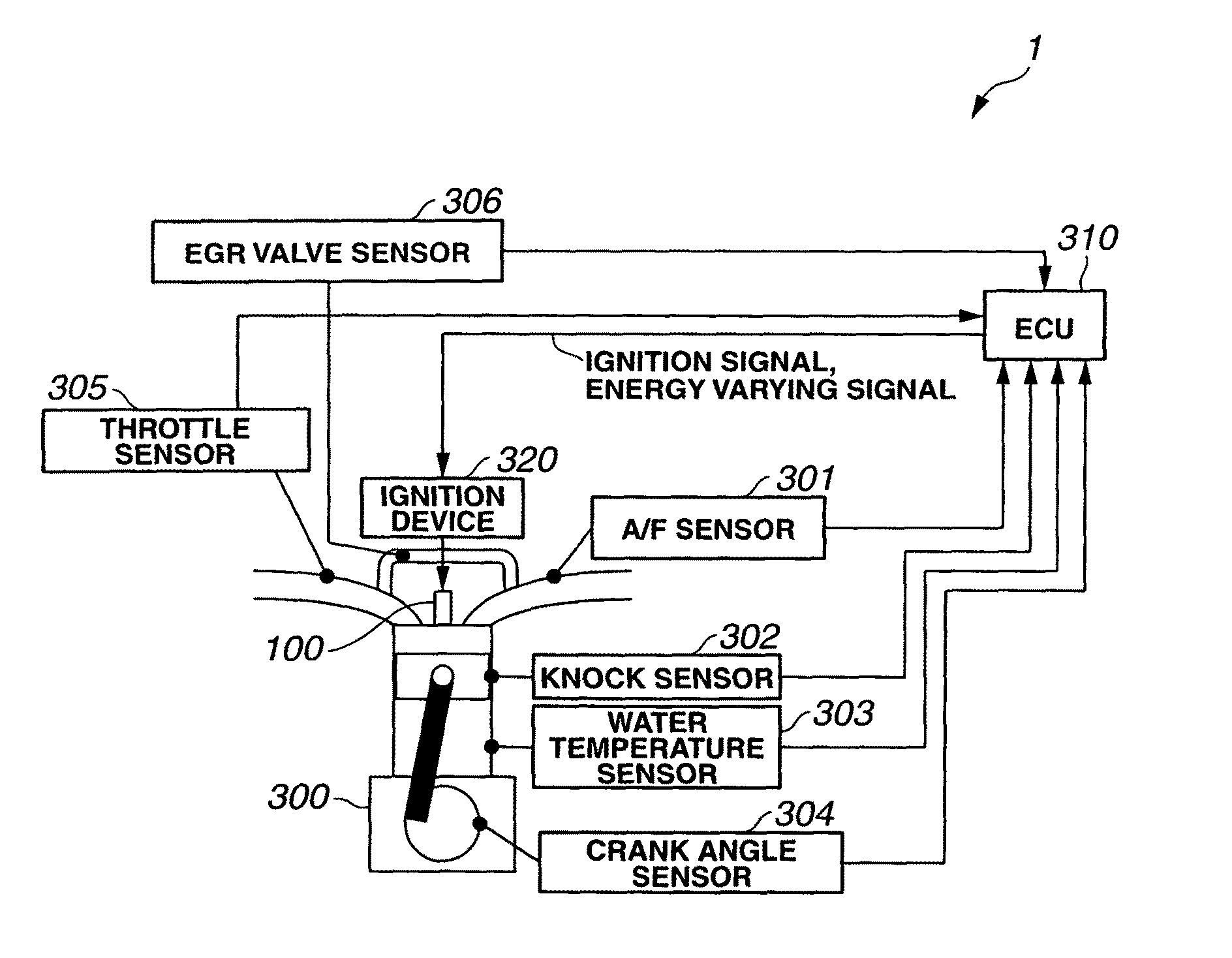
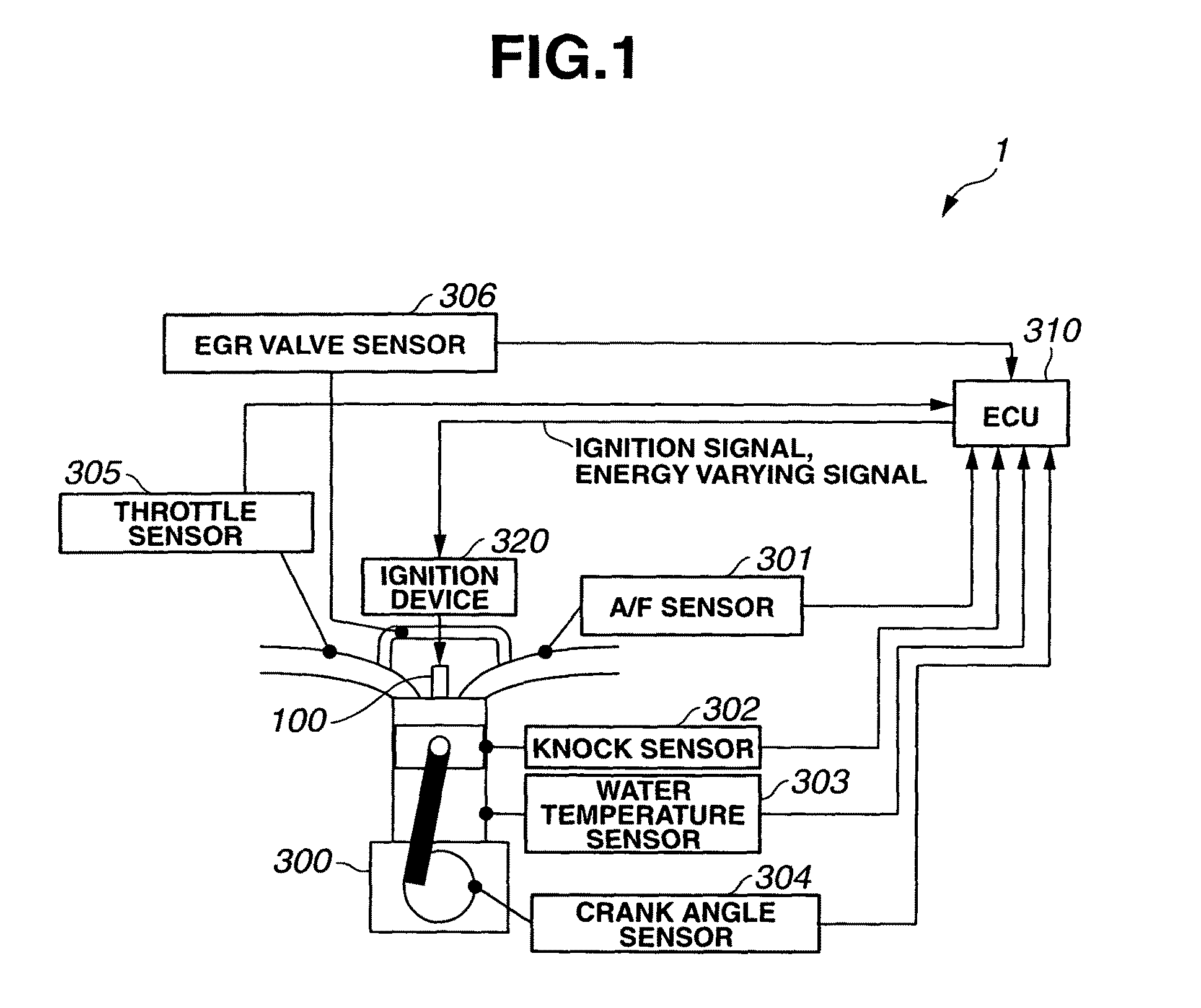
[0060]FIG. 1 is a view for illustrating a control system for controlling the ignition of a plasma-jet spark plug in outline. The control system 1 shown in FIG. 1 includes an internal combustion engine 300 provided with a plasma-jet spark plug 100, an ignition device 320 to perform an ignition of the plasma-jet spark plug 100, various sensors to sense one or more operating conditions of internal combustion engine 300, and an ECU (Engine Control Unit) 310 connected with these sensors.

[0061]Internal combustion engine 300 is an ordinary four stroke gasoline engine. Internal combustion ...


PUM


Abstract

A control system for controlling the ignition of a plasma-jet spark plug provided in an internal combustion engine senses an operating condition of the internal combustion engine, and determines an ignition mode of the plasma-jet spark plug in accordance with the sensed operating condition. The control system performs an ignition control of breaking down the insulation across a spark discharge gap by applying a first electric power to the plasma-jet spark plug, and producing plasma in the vicinity of the spark discharge gap by applying a second electric power to the spark discharge gap in a state of dielectric breakdown. The control system performs this ignition control according to the ignition mode determined as mentioned above.

Description

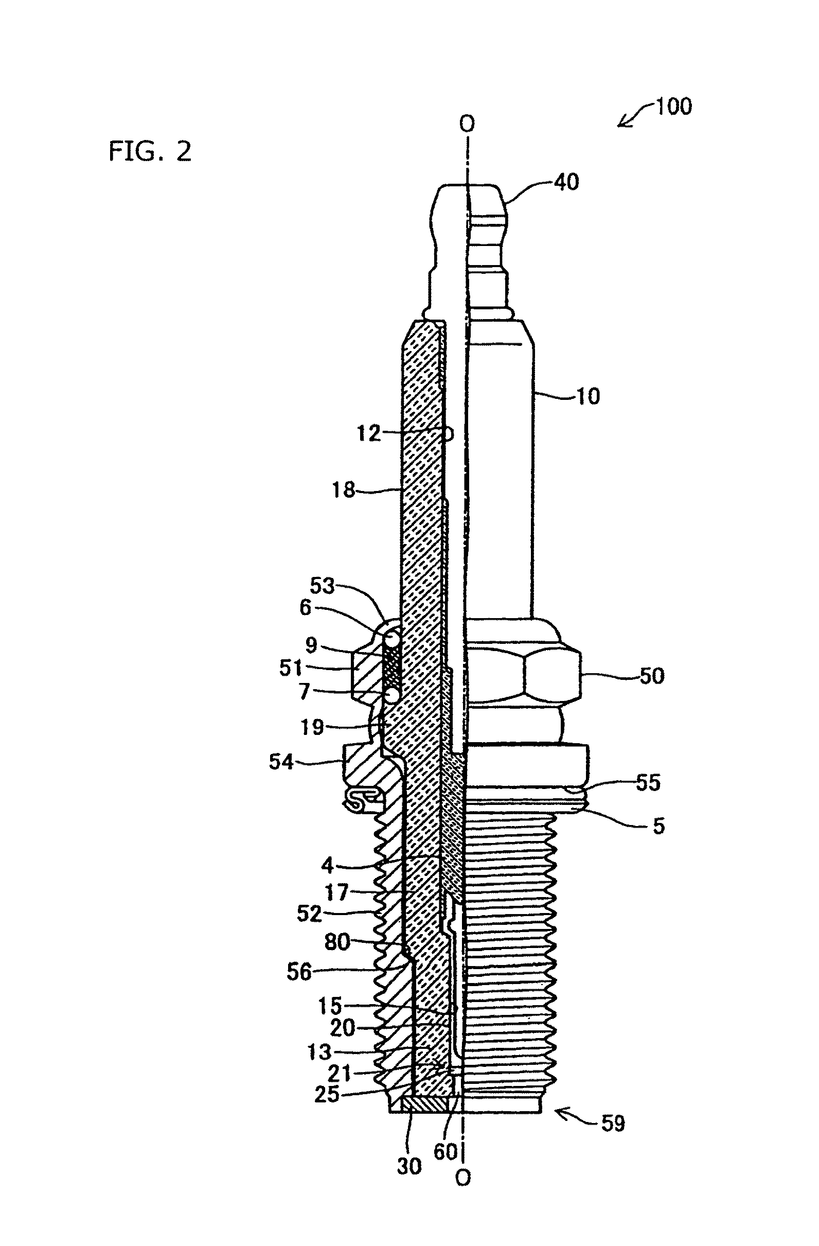
TECHNICAL FIELD[0001]The present invention relates to technique of controlling a plasma-jet spark plug arranged to produce plasma to ignite a mixture gas, for an internal combustion engine.BACKGROUND ART[0002]A spark plug for igniting a mixture gas with a spark discharge is used conventionally for an engine or an internal combustion engine for a motor vehicle. Recently, there is a demand for higher output and lower fuel consumption of an internal combustion engine. Accordingly, development is in progress for a plasma-jet spark plug capable of providing faster propagation of combustion, and igniting a lean mixture gas for higher ignition limit air fuel ratio (cf. patent document 1, for example).[0003]Patent document 1: JP 2007-287666 A[0004]The plasma-jet spark plug has a structure including a discharge space (cavity) of a small volume formed by an insulator, such as ceramic insulator, surrounding a spark discharge gap between a center electrode and a ground electrode. In one example...

Claims


Application Information

Patent Timeline
Patent Type & Authority Patents(United States)
IPC IPC(8): F02P5/00F02P7/02
CPCF02P9/007H01T13/50
Inventor SATO, YOSHIKUNINAKANO, DAISUKEYAMADA, YUICHINAKAMURA, TORU
Owner NGK SPARK PLUG CO LTD
Learn More