
Perpendicular magnetic recording head and method of manufacturing the same

a technology of perpendicular magnetic recording head and manufacturing method, which is applied in the manufacture of head surface, instruments, data recording, etc., can solve the problems of weakened recording magnetic field and decrease in coil turn number, and achieve the effect of improving high-frequency recording characteristics

Inactive Publication Date: 2012-11-20
SEAGATE TECH INT
View PDF29 Cites 4 Cited by
  • Summary
  • Abstract
  • Description
  • Claims
  • Application Information

AI Technical Summary

Benefits of technology

"The present invention provides a perpendicular magnetic recording head with improved high-frequency recording characteristics for high-density magnetic recording. The head has a structure that includes a main pole, a coil, and a return yoke. The coil is wound in a solenoid or planar spiral shape around the main pole, and the number of times the coil passes in front of the return yoke is smaller than the number of times it passes behind the return yoke. This results in a more efficient magnetic field for recording information on the recording medium. The manufacturing method involves sequentially forming layers and using an etch mask to create the pole tip and the return yoke. The technical effects of the invention include improved recording characteristics, higher data storage capacity, and better performance of the perpendicular magnetic recording head."

Problems solved by technology

However, a shorter yoke generally results in a decrease of the number of coil turns, and thus the recording magnetic field is weakened.

Method used


Image

  • Perpendicular magnetic recording head and method of manufacturing the same
  • Perpendicular magnetic recording head and method of manufacturing the same
  • Perpendicular magnetic recording head and method of manufacturing the same

Examples


Embodiment Construction

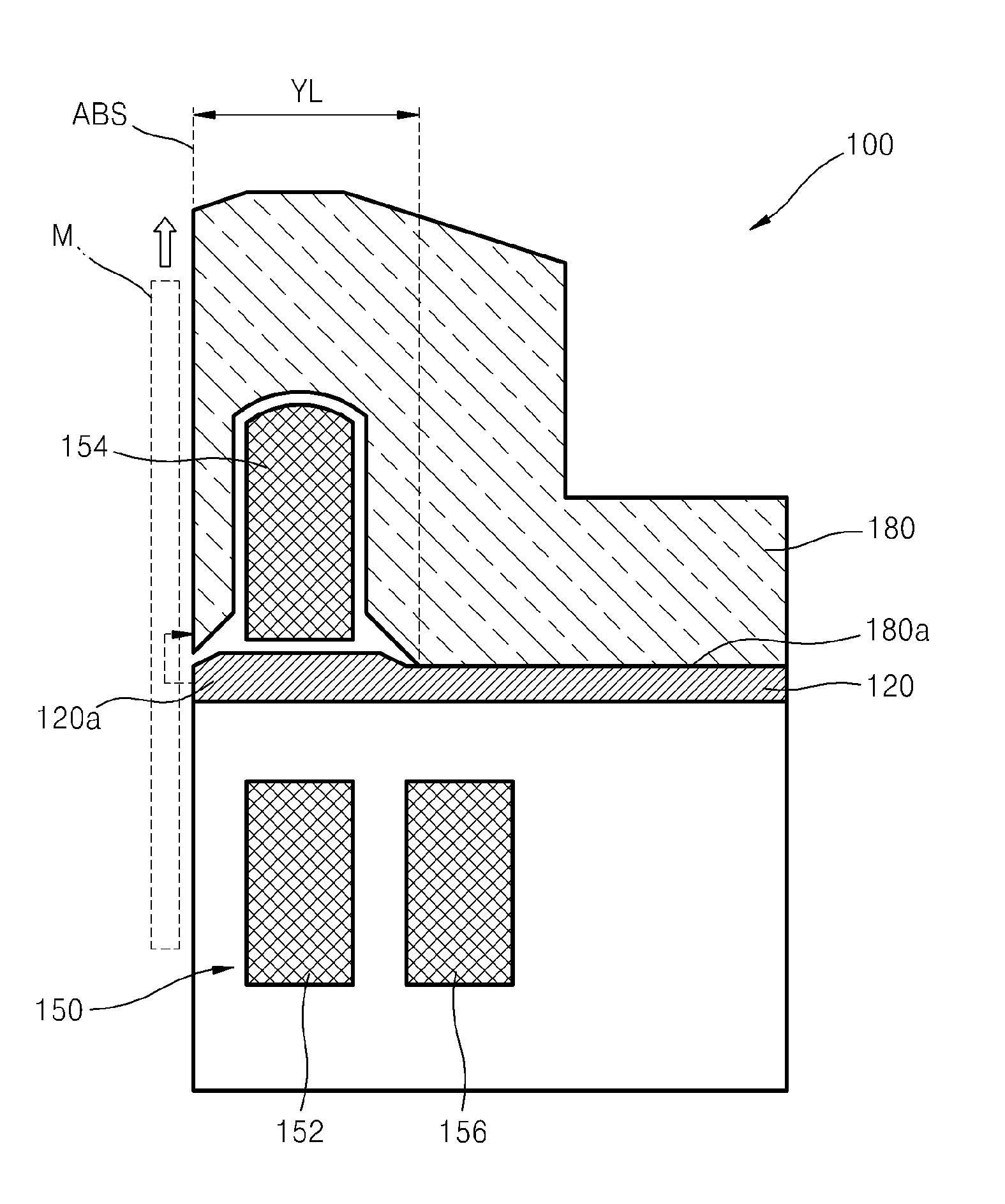
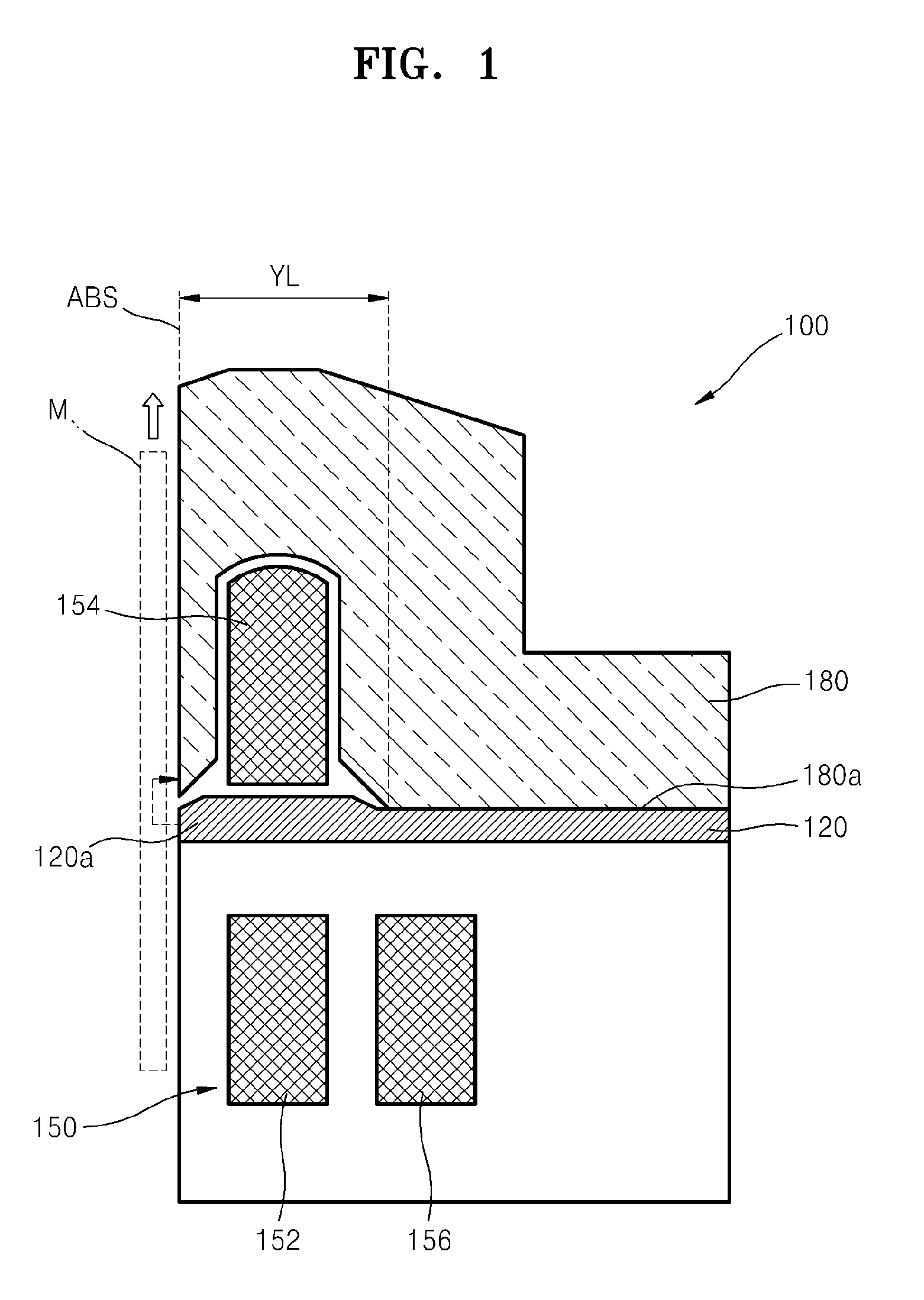
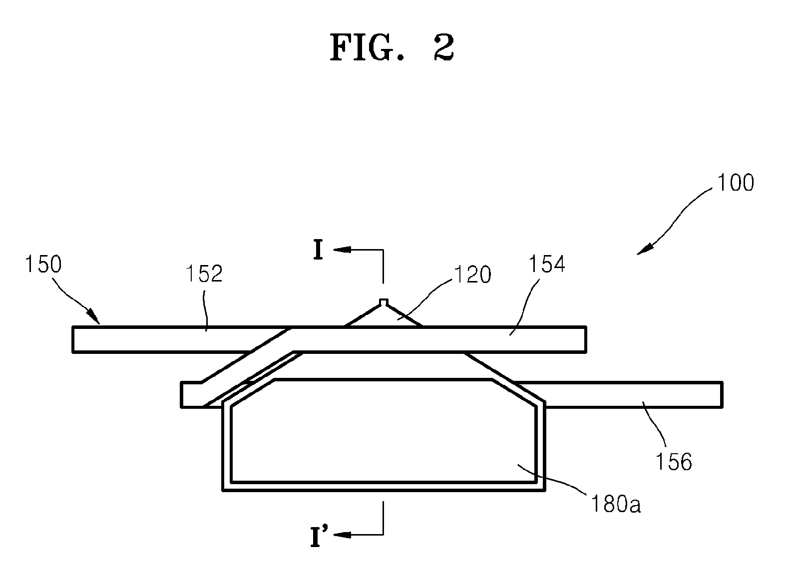
[0019]FIG. 1 is a sectional view of a perpendicular magnetic recording head 100, and FIG. 2 is a plan view of the perpendicular magnetic recording head 100. FIG. 1 corresponds to a sectional view cut along line I-I′ in FIG. 2. In FIG. 2, to illustrate a structure of a coil 150 in detail, only a connecting part 180a at which a return yoke 180 is connected to a main pole 120 is shown and the return yoke 180 is omitted.

[0020]Referring to FIGS. 1 and 2, the perpendicular magnetic recording head 100 includes the main pole 120 applying a recording magnetic field toward a recording medium M, the coil 150 to which a voltage is applied such that the recording magnetic field for recording information in the recording medium M is generated from the main pole 120, and the return yoke 180 forming a magnetic path for the recording magnetic field together with the main pole 120.

[0021]The perpendicular magnetic recording head 100 moves along a downtrack direction relatively to the recording medium ...


PUM

PropertyMeasurementUnit
saturation magnetic flux densityaaaaaaaaaa
longitudinal magnetic recording methodaaaaaaaaaa
recording densityaaaaaaaaaa

Abstract

Provided are a perpendicular magnetic recording head and a method of manufacturing the same. The perpendicular magnetic recording head includes a main pole including a pole tip applying a recording magnetic field to a recording medium, a coil surrounding the main pole in a solenoid shape such that recording magnetic field for recording information to a recording medium is generated at the pole tip, and a return yoke forming a magnetic path for the recording magnetic field together with the main pole and surrounding a portion of the coil passing above the main pole. The number of times that the coil passes above the main pole is smaller than the number of times that the coil passes below the main pole.

Description

CROSS-REFERENCE TO RELATED PATENT APPLICATION[0001]This application claims the benefit of Korean Patent Application No. 10-2007-0113188, filed on Nov. 7, 2007, in the Korean Intellectual Property Office, the disclosure of which is incorporated herein in its entirety by reference.BACKGROUND OF THE INVENTION[0002]1. Field of the Invention[0003]The present invention relates to a perpendicular magnetic recording head recording information via a perpendicular magnetic recording method, and a method of manufacturing the perpendicular magnetic recording head.[0004]2. Description of the Related Art[0005]There are two types of magnetic recording methods: a longitudinal magnetic recording method and a perpendicular magnetic recording method. In the longitudinal magnetic recording method, information is recorded by magnetizing of a magnetic layer in a direction parallel to a surface of the magnetic layer; in the perpendicular magnetic recording method, information is recorded by magnetizing of...

Claims


Application Information

Patent Timeline
Patent Type & Authority Patents(United States)
IPC IPC(8): G11B5/127
CPCG11B5/1278G11B5/17G11B5/3116G11B5/3123G11B5/3163G11B5/33G11B5/187G11B5/127
Inventor LEE, JOO-HOSUNWOO, KOOK-HYUNKIM, EUN-SIKNA, KYOUNG-WONLEE, SANG-HUN
Owner SEAGATE TECH INT
Learn More