
Electrochemical biosensor measuring system

a biosensor and electrochemical technology, applied in the direction of diaphragms, cells, immobilised enzymes, etc., can solve the problems of difficult practical application, inconvenient post-processing, technical and economic difficulties, etc., to ensure economic efficiency, convenient and accurate acquisition, and simple construction

Inactive Publication Date: 2012-11-20
I SENS INC
View PDF15 Cites 3 Cited by
  • Summary
  • Abstract
  • Description
  • Claims
  • Application Information

AI Technical Summary

Benefits of technology

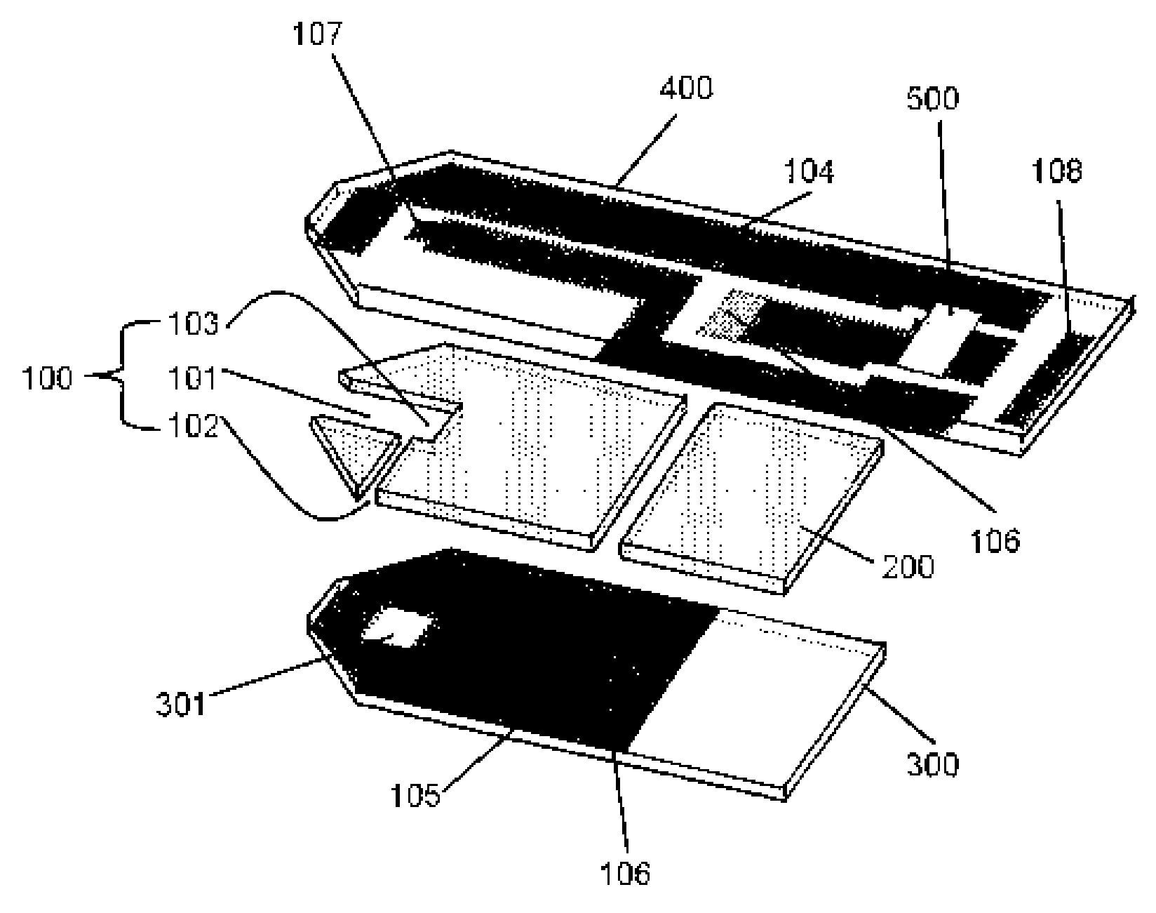
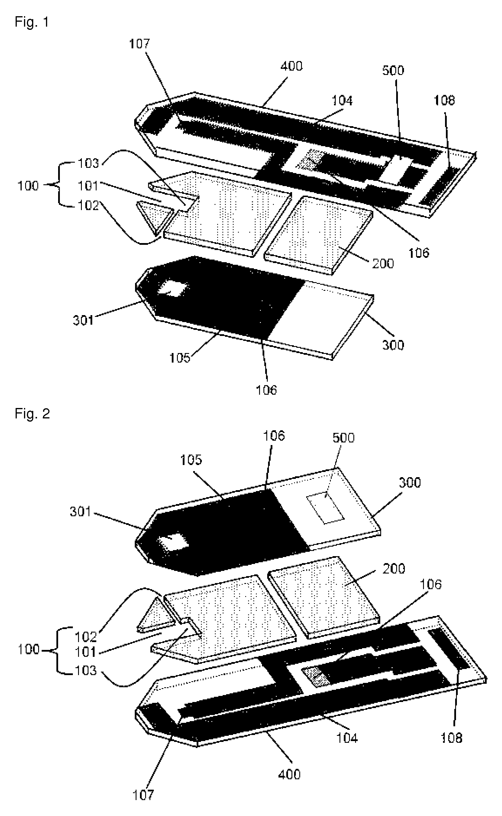
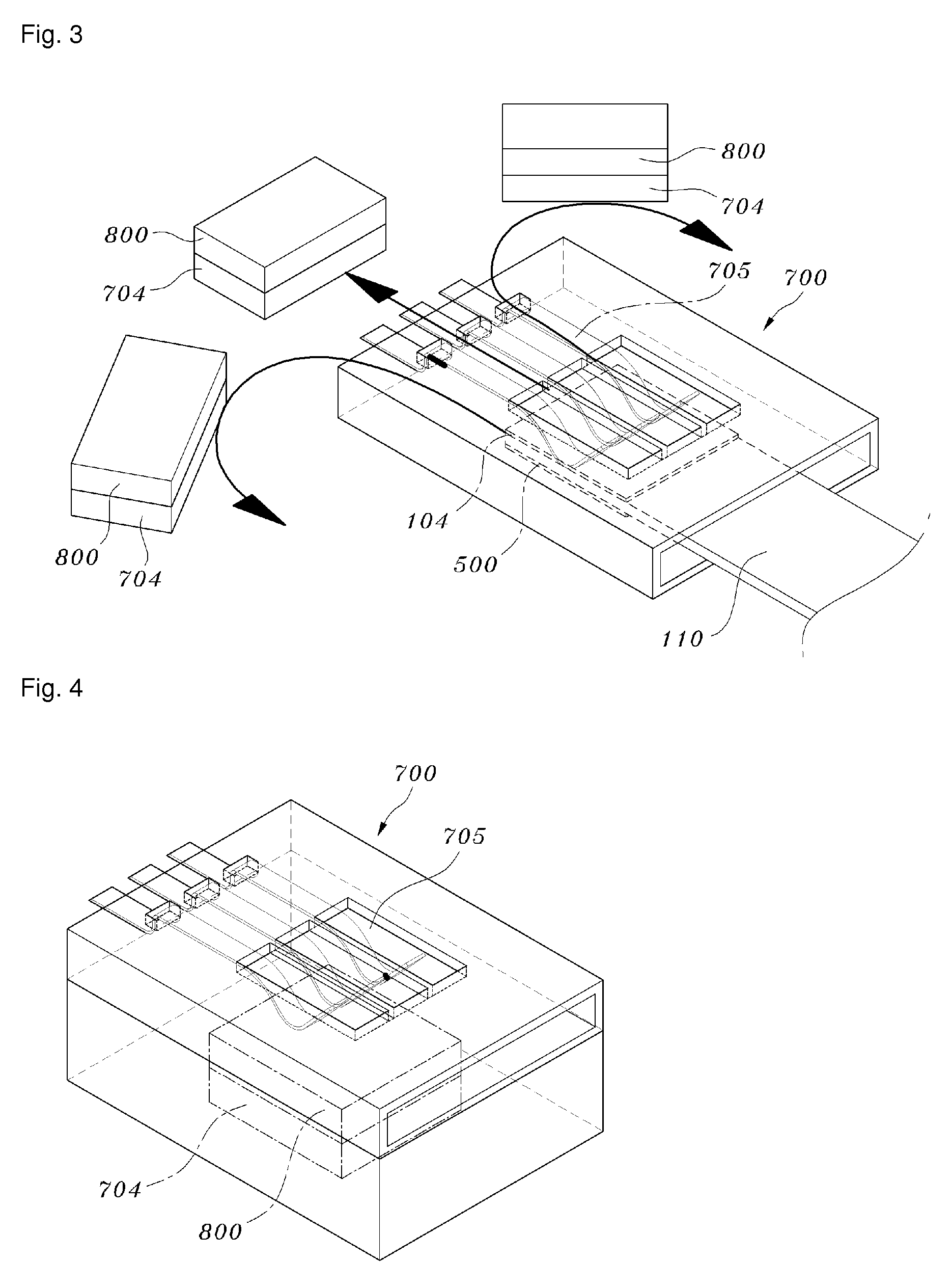
[0018]The electrochemical biosensor comprises a production lot information identification portion on which information is recorded in a magnetization mark, and the measuring device can automatically identify the production lot information of the biosensor upon the insertion of the electrochemical biosensor into the measuring device. The electrochemical biosensor and the measuring device thereof in accordance with the present invention can record production lot information in the form of magnetization marks on an electrochemical biosensor strip and read the information as digital signals through a magnetoresistance sensor device, which can be mounted on the surface of a circuit board using Surface Mounted Technology (SMT). Without the need for a high-priced filter or a complicated calculation system, the magnetic detector system has a simple construction and ensures economic efficiency in the construction of the measuring device. Also, the measuring device automatically identifies the production lot information recorded on the biosensor, so that the frequency of inconvenience and error, which occur when a user personally inputs the production lot information, can be reduced, with the result that the measured values can be conveniently and accurately acquired.

Problems solved by technology

However, this method is highly inconvenient for the user and causes the user to make input errors, thus leading to inaccurate results.
However, these methods serve to accurately adjust resistance, and require a process of mass-producing the sensors first, measuring the statistical characteristics of the sensors, and post-processing the measured information again using a method of adjusting the resistance marked on the sensors.
However, the process of accurately adjusting the resistance, marked in large quantities, through the post-processing is very inconvenient, and is difficult to use for practical application.
These methods, using color or bar codes, are favorable for a colorimetric method-based sensor using the spectrum system, but they have technical and economic difficulties when applied to systems using an electrochemical measurement mechanism.
For example, the size and structure of the portion where the electrochemical sensor strip is inserted into the measuring device for the purpose of electrical connection, that is, the connection space of the sensor strip, is very limited when constructing a device and circuit for spectroscopically identifying the structure into which the production lot information is input.
Further, color discrimination requires a process of scattering and identifying various wavelengths of light detected using a detector and a complicated process, that is, the conversion of analog signals into digital signals and the calculation thereof, with the concomitant accompaniment of a device and its program therefor.
Thus, the expenses incurred when constructing the system are greatly increased.
However, this method also has a possibility of causing the user to make an error of incorrectly reading a code recorded on the container.

Method used


Image

  • Electrochemical biosensor measuring system
  • Electrochemical biosensor measuring system
  • Electrochemical biosensor measuring system

Examples


Embodiment Construction

[0042]In the present specification, the term “biosensor” is used as having the same meaning as the term “biosensor strip”.

[0043]In accordance with an aspect thereof, the present invention provides an electrochemical biosensor, composed of an electrodes including a working electrode and an auxiliary electrode prepared on at least two insulating plates; a capillary sample cell for introducing a sample into the electrodes; a reaction reagent layer, formed on the working electrode, containing an oxidation enzyme and an electron transfer mediator; an electrical connection portion for connecting the working electrode and the auxiliary electrode; and a production lot information identification portion, configured such that production lot information is recorded on at least one insulating plate, which is selected from among at least two planar insulating plates and does not interrupt connection between the electrodes, wherein the production lot information identification portion, on which t...


PUM

PropertyMeasurementUnit
thickaaaaaaaaaa
sizeaaaaaaaaaa
magnetic field intensityaaaaaaaaaa

Abstract

Disclosed are an electrochemical biosensor which comprises a production lot information identification portion, on which information is recorded in a magnetization mark, and a measuring device which can automatically identify the production lot information of the biosensor with the insertion of the electrochemical biosensor into the measuring device. The electrochemical biosensor and the measuring device thereof can record production lot information in the form of magnetization marks on an electrochemical biosensor strip and read the information as digital signals through a magnetoresistance sensor device, which can be mounted on the surface of a circuit board using Surface Mounted Technology (SMT). Without the need for a high-priced filter or a complicated calculation system, the magnetic detector system has a simple construction and realizes economic efficiency in the construction of the measuring device. Also, the measuring device automatically identifies the production lot information recorded on the biosensor, so that inconvenience and the frequency of errors, which occur when a user personally inputs the production lot information, can be reduced, with the result that the measured values can be conveniently and accurately acquired.

Description

RELATED APPLICATIONS[0001]This application is a 35 U.S.C. §371 national stage filing of PCT Application No. PCT / KR2008 / 001106 filed on Feb. 26, 2008, which claims priority to, and the benefit of, Korean Patent Application No. 10-2007-0080588 filed on Aug. 10, 2007. The contents of the aforementioned applications are hereby incorporated by reference.TECHNICAL FIELD[0002]The present invention relates to an electrochemical biosensor and a biosensor measuring device.BACKGROUND ART[0003]For the diagnosis and prophylaxis of diabetes mellitus, the importance of periodic monitoring of blood glucose levels has been increasingly emphasized. Nowadays, strip-type biosensors designed for hand-held reading devices allow individuals to readily monitor glucose levels in the blood.[0004]A large number of commercialized biosensors measure blood glucose present in blood samples using an electrochemical technique. The principle of the electrochemical technique is based on the following Reaction 1.Gluco...

Claims


Application Information

Patent Timeline
Patent Type & Authority Patents(United States)
IPC IPC(8): G01V3/00
CPCG01N33/48771C12Q1/004A61B5/14532A61B5/1486G01N27/72G01N33/48
Inventor CUI, GANGKIM, KEUN KIHAN, DONG HOONKIM, MOON HWANNAM, HAKHYUNCHA, GEUN SIG
Owner I SENS INC
Learn More