
Control moment gyroscope based momentum control systems in small satellites

a technology of gyroscope and control system, which is applied in the direction of instruments, cosmonautic vehicles, transportation and packaging, etc., can solve the problems of inability to accelerate a small satellite to this slew rate, inability to produce torque for rwa's, and inability to accelerate a small satellite for over 60 seconds,

Active Publication Date: 2012-11-20
HONEYWELL INT INC
View PDF32 Cites 17 Cited by
  • Summary
  • Abstract
  • Description
  • Claims
  • Application Information

AI Technical Summary

Problems solved by technology

However, RWA's have an inherently low torque producing capability and may take over 60 seconds to accelerate a small satellite to this slew rate, which is unacceptably long.
16″ disk diameter), their relatively large mass and their power consumption, these devices have historically been impractical for use with small satellites (i.e. <400 kg).
Therefore, CMG size is an issue.

Method used


Image

  • Control moment gyroscope based momentum control systems in small satellites
  • Control moment gyroscope based momentum control systems in small satellites
  • Control moment gyroscope based momentum control systems in small satellites

Examples


Embodiment Construction

[0021]The following detailed description is merely exemplary in nature and is not intended to limit the invention or the application and uses of the invention. Furthermore, there is no intention to be bound by any theory presented in the preceding background or the following detailed description.

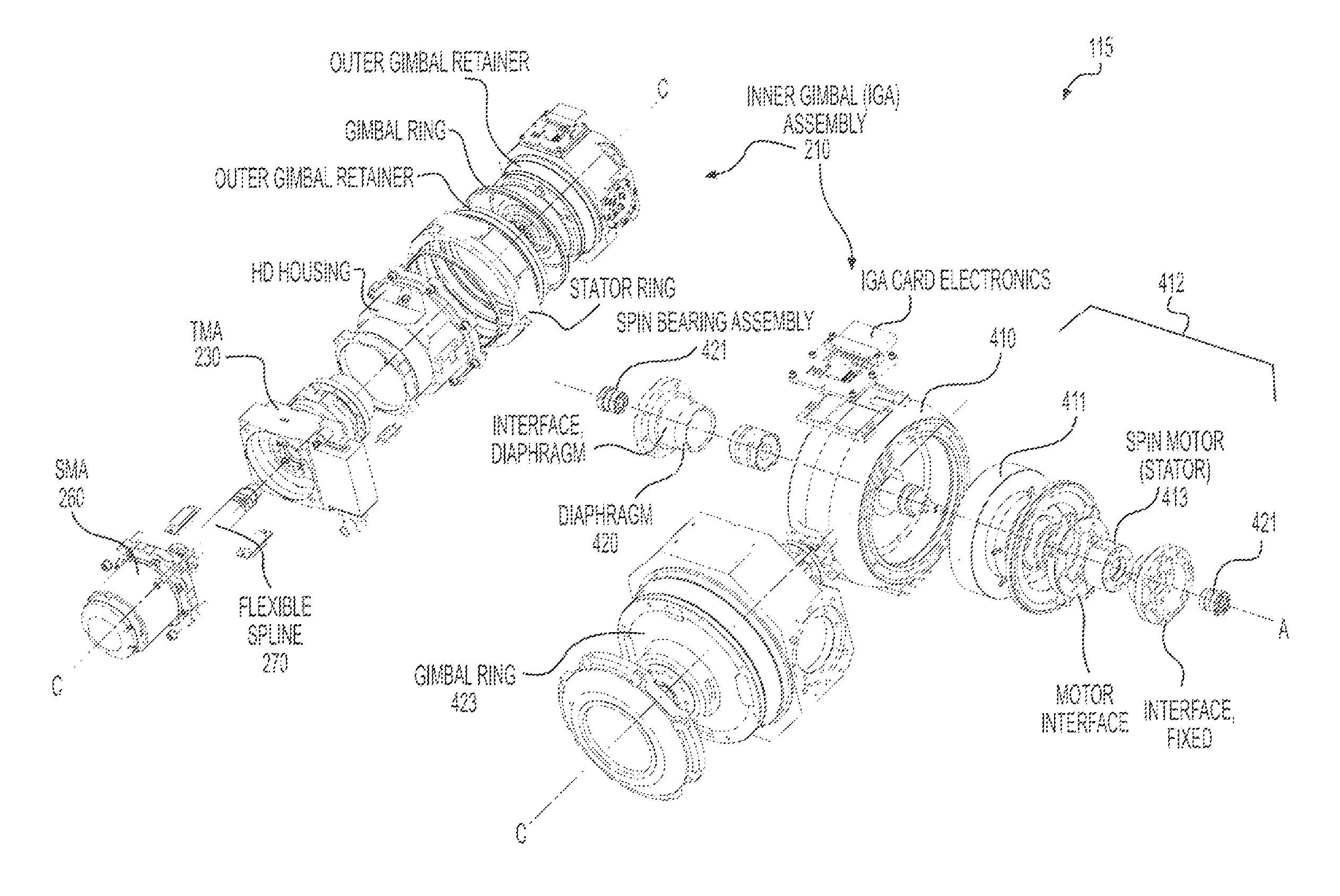
[0022]The following disclosure describes a momentum control system (MCS) for small spacecraft. It is well known in the art that a minimum of three gyroscopes are required to fully control the attitude of an object in space such as a satellite. A gyroscope operates by spinning a momentum rotor mounted within in a gimbal thereby creating an angular momentum within the rotor. By Newton's first law of motion, the rotor maintains a constant velocity until an outside force imparts energy that changes the direction or magnitude of the velocity. Conversely, by applying a force against a rigidly mounted spinning gyro, the gyroscope creates an equal and opposite reactive force which changes the attitu...


PUM


Abstract

A self-contained momentum control system (MCS) for a spacecraft is provided for small satellites. The MCS features a miniaturized gyroscopic rotor with a rotational speed in excess of 20,000 RPM. The MCS includes at least three control moment gyroscopic mechanical assemblies (CMAs) rigidly mounted within a single enclosure, where each CMA mounted in an orientation whereby the longitudinal axis of each CMA is either orthogonal to every other CMA or is parallel to another CMA but in the opposite orientation. In order to further reduce the size of the MCS, an electronics package that is configured to interface command and control signals with and to provide power to the CMAs is included within the MCS enclosure. A plurality of shock isolation devices are used to secure each of the CMAs to the enclosure in order to reduce the launch load upon the CMAs thereby allowing the use of smaller rotor spin bearings. The MCS enclosure surrounding the CMAs and support structure is hermetically sealed.

Description

PRIORITY CLAIMS[0001]This application claims the benefit of U.S. Provisional Application No. 61 / 218,291, filed Jun. 18, 2009, and U.S. Provisional Application and is herein incorporated by reference in its entirety.STATEMENT REGARDING FEDERALLY SPONSORED RESEARCH OR DEVELOPMENT[0002]This invention was made with Government support under Contract FA9453-08-C-0247 awarded by the United States Air Force. The Government has certain rights in this invention.BACKGROUND[0003]Improved attitude agility in small satellites increases their value by improving their data collection rate and increasing the time available for transmission of that data to the ground. This is so because a time lag exists as the satellite progresses from one attitude to another for collection or transmission of the data. The longer the progression time, the shorter the time available for data collection and transmission.[0004]The current state-of-the art in agile small satellites allows for slew rates of less than 1° / ...

Claims


Application Information

Patent Timeline
Patent Type & Authority Patents(United States)
IPC IPC(8): G01C19/06
CPCB64G1/286Y10T74/1229Y10T74/1225Y10T74/1282
Inventor MCMICKELL, BRETTBUCHELE, PAULGISLER, GARY LYNWOODANDRUS, JAMES
Owner HONEYWELL INT INC
Learn More