
Reduced delay spatial coding and decoding apparatus and teleconferencing system

a teleconferencing technology, applied in the field of reduced delay spatial coding and decoding apparatus and teleconferencing system, can solve the problems of high cost of bidirectional communication, difficulty in maintaining sound quality high enough to convey realistic sensations, and provide less communication cost. , the effect of reducing the delay of algorithm

Inactive Publication Date: 2012-11-13
PANASONIC CORP
View PDF21 Cites 2 Cited by
  • Summary
  • Abstract
  • Description
  • Claims
  • Application Information

AI Technical Summary

Benefits of technology

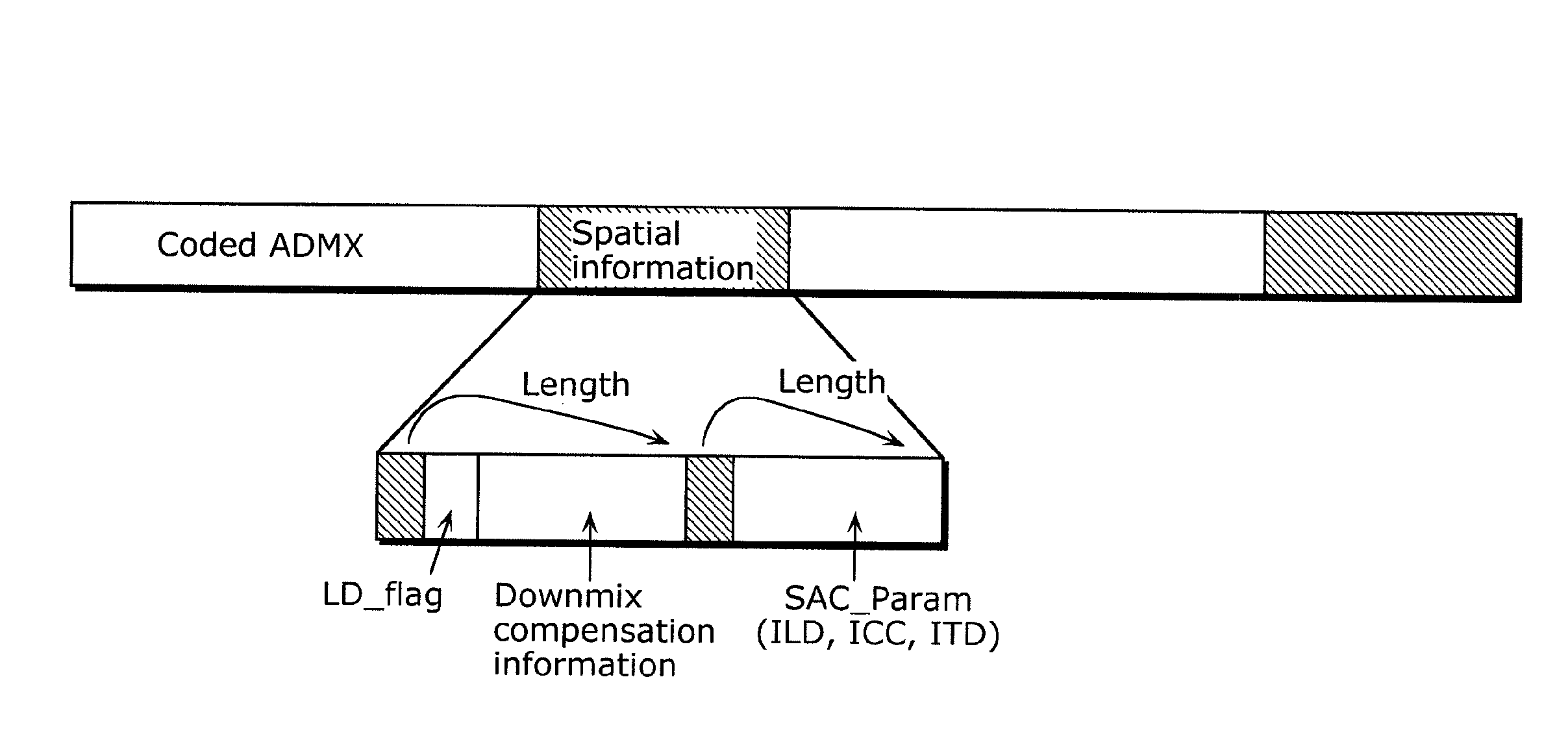
[0090]The audio coding apparatus and the audio decoding apparatus according to the present invention can reduce the algorithm delay occurring in a conventional multi-channel audio coding apparatus and a conventional multi-channel audio decoding apparatus, and maintain a relationship between a bit rate and sound quality that is in a trade-off relationship, at high levels.
[0091]In other words, the present invention can reduce the algorithm delay much more than that by the conventional multi-channel audio coding technique, and thus has an advantage of enabling the construction of e.g., a teleconferencing system that provides a real-time communication and a communication system which brings realistic sensations and in which transmission of a multi-channel audio signal with lower delay and high sound quality is a must.
[0092]Accordingly, the present invention makes it possible to transmit and receive a signal with higher sound quality and lower delay and at a lower bit rate. Thus, the present invention is highly suitable for practical use, in recent days where mobile devices, such as cellular phones bring communications with realistic sensations and audio-visual devices and teleconferencing systems have widely spread the full-fledged communication with realistic sensations. The application is not limited to these devices, and obviously, the present invention is effective for overall bidirectional communications in which lower delay amount is a must.

Problems solved by technology

Additionally, the other problem is that the bidirectional communication is costly.
Since sound extremely degrades according to a decrease in a bit rate in accordance with e.g., the MPEG-AAC standard and the Dolby digital standard, the difficulty lies in maintaining sound quality high enough to convey realistic sensations and provide less communication cost.

Method used


Image

  • Reduced delay spatial coding and decoding apparatus and teleconferencing system
  • Reduced delay spatial coding and decoding apparatus and teleconferencing system
  • Reduced delay spatial coding and decoding apparatus and teleconferencing system

Examples


embodiment 1

[Embodiment 1]

[0103]First, Embodiment 1 in the present invention will be described.

[0104]FIG. 1 illustrates an audio coding apparatus according to Embodiment 1 in the present invention. Furthermore, a delay amount is shown under each constituent element in FIG. 1. The delay amount corresponds to a time period between storage of input signals and output signals. When no plural input signals is stored between an input and an output, the delay amount that is negligible is denoted as “0” in FIG. 1.

[0105]The audio coding apparatus in FIG. 1 is an audio coding apparatus that codes a multi-channel audio signal, and includes a downmix signal generating unit 410, a downmix signal coding unit 404, a first t-f converting unit 401, an SAC analyzing unit 402, a second t-f converting unit 405, a downmix compensation circuit 406, and a multiplexing device 407. The downmix signal generating unit 410 includes an arbitrary downmix circuit 403. The SAC analyzing unit 402 includes a downmixing unit 408...

embodiment 2

(Embodiment 2)

[0194]Hereinafter, a downmix compensation circuit and a downmix adjustment circuit according to Embodiment 2 in the present invention will be described with reference to the drawings.

[0195]Although the base configurations of an audio coding apparatus and an audio decoding apparatus according to Embodiment 2 are the same as those of the audio coding apparatus and the audio decoding apparatus according to Embodiment 1 that are shown in FIGS. 1 and 4, operations of the downmix compensation circuit 406 are different in Embodiment 2, which will be described in detail hereinafter.

[0196]The operations of the downmix compensation circuit 406 according to Embodiment 2 will be described.

[0197]First, the significance of the downmix compensation circuit 406 in Embodiment 2 will be described by pointing out the problems in the prior art.

[0198]FIG. 8 illustrates a configuration of a conventional SAC coding apparatus.

[0199]The downmixing unit 203 downmixes a multi-channel audio signa...

embodiment 3

(Embodiment 3)

[0220]Hereinafter, a downmix compensation circuit and a downmix adjustment circuit according to Embodiment 3 in the present invention will be described with reference to the drawings.

[0221]Although the base configurations of an audio coding apparatus and an audio decoding apparatus according to Embodiment 3 are the same as those of the audio coding apparatus and the audio decoding apparatus according to Embodiment 1 that are illustrated in FIGS. 1 and 4, operations of the downmix compensation circuit 406 are different in Embodiment 3, which will be described in detail hereinafter.

[0222]The operations of the downmix compensation circuit 406 according to Embodiment 3 will be described.

[0223]First, the significance of the downmix compensation circuit 406 in Embodiment 3 will be described by pointing out the problems in the prior art.

[0224]FIG. 8 illustrates the configuration of the conventional SAC coding apparatus.

[0225]The downmixing unit 203 downmixes a multi-channel a...


PUM


Abstract

The delay in a multi-channel audio coding apparatus and a multi-channel audio decoding apparatus is reduced. The audio coding apparatus includes: a downmix signal generating unit that generates, in a time domain, a first downmix signal that is one of a 1-channel audio signal and a 2-channel audio signal from an input multi-channel audio signal; a downmix signal coding unit that codes the first downmix signal; a first t-f converting unit that converts the input multi-channel audio signal into a multi-channel audio signal in a frequency domain; and a spatial information calculating unit that generates spatial information for generating a multi-channel audio signal from a downmix signal.

Description

TECHNICAL FIELD[0001]The present invention relates to an apparatus that implements coding and decoding with a lower delay, using a multi-channel audio coding technique and a multi-channel audio decoding technique, respectively. The present invention is applicable to, for example, a home theater system, a car stereo system, an electronic game system, a teleconferencing system, and a cellular phone.BACKGROUND ART[0002]The standards for coding multi-channel audio signals include the Dolby digital standard and Moving Picture Experts Group-Advanced Audio Coding (MPEG-AAC) standard. These coding standards implement transmission of the multi-channel audio signals by basically coding an audio signal of each channel in the multi-channel audio signals separately. These coding standards are referred to as discrete multi-channel coding, and the discrete multi-channel coding enables coding signals for 5.1 channel practically at a bit rate around 384 kbps as the lowest limit.[0003]On the other ha...

Claims


Application Information

Patent Timeline
Patent Type & Authority Patents(United States)
IPC IPC(8): G10L21/00G10L19/02H04R5/00G10L19/00G10L19/008
CPCG10L19/008
Inventor ISHIKAWA, TOMOKAZUNORIMATSU, TAKESHICHONG, KOK SENGZHOU, HUAN
Owner PANASONIC CORP
Learn More