Machine element

a technology of machine elements and elements, applied in the direction of bearing components, shafts, gearing details, etc., can solve the problems of relatively high material cost and high force during forming, low degree of freedom in the design of shaped elements, and relatively complex production of planetary pins of the prior art. achieve the effect of producing simply and inexpensively

Inactive Publication Date: 2012-11-06
SCHAEFFLER TECH AG & CO KG
View PDF38 Cites 2 Cited by
  • Summary
  • Abstract
  • Description
  • Claims
  • Application Information

AI Technical Summary

Benefits of technology

[0005]It is therefore the object of the invention to provide a machine part, by way of which the abovementioned disadvantages can be avoided and which can be produced simply and inexpensively.SUMMARY OF THE INVENTION
[0017]As an alternative, the surface of the cylindrical surfaces keeps the quality which it has after forming without the removal of material.
[0019]The advantages of machine elements of this type according to the invention lie, in particular, in their simple and inexpensive production, in the low weight and in their versatile use. Since the machine elements are assembled, relatively complicated contours can be produced with low outlay by the fact that different individual structures of the complicated contour can be produced on different ones of the elements which are manufactured separately from one another, and can then be assembled to form the machine element with the complicated contour. Moreover, the elements can be combined with one another according to the modular principle in any desired way to form different machine elements.

Problems solved by technology

The planetary pins of the prior art are therefore relatively complex to produce.
Such rotationally symmetrical machine elements made from sheet metal which are hollow on the inside permit low degrees of freedom in the design of their shaped elements, since they have to have axial demolding openings for pulling them off from or out of the forming die after the forming operations.
In order to ensure appropriate rigidity of the gearwheels under load, the gearwheels are open on one side and the material for their production has to be of correspondingly thick configuration, with the result that relatively high material costs and high forces during the forming are produced.
In turn, the latter has a disadvantageous effect on the die costs.

Method used


Image

  • Machine element
  • Machine element
  • Machine element

Examples


Embodiment Construction

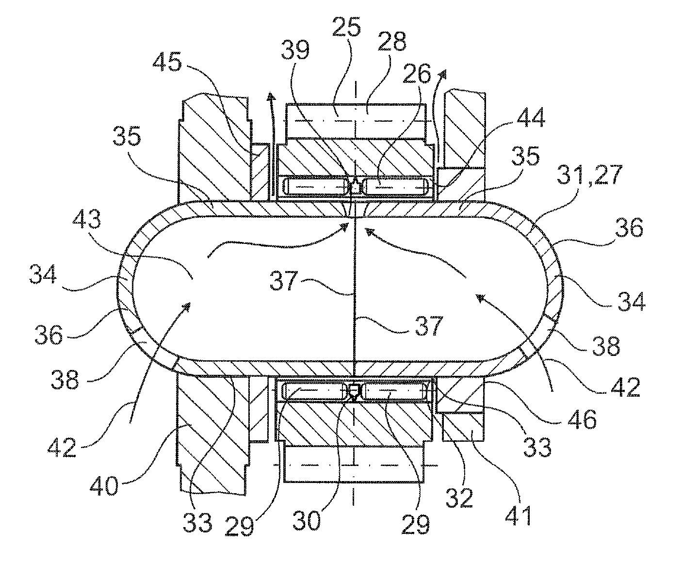
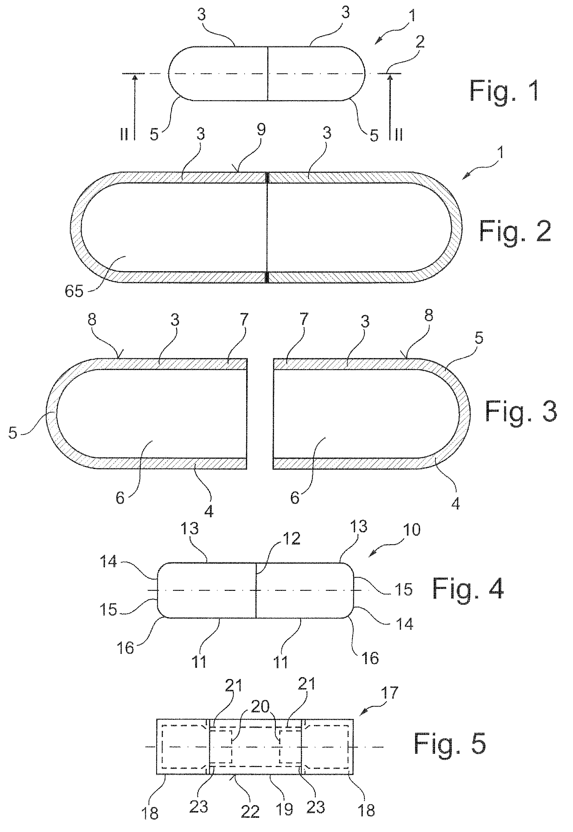
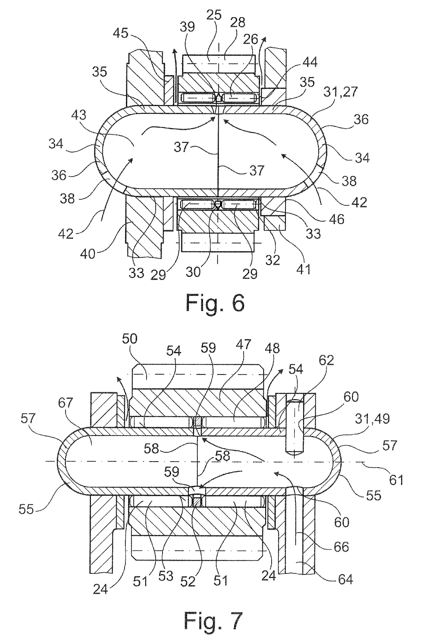
[0033]FIGS. 1, 2 and 3—FIG. 1 shows a machine element 1 which may be configured as a planetary pin, in a side view. FIG. 2 shows a longitudinal section along the axis of symmetry 2 of the machine element 1 of rotationally symmetrical configuration. The machine element 1 is assembled from two elements 3 and is closed axially on the end sides by the bases 5. The elements 3 together enclose a cavity 65.

[0034]The elements 3 are shown as individual parts in FIG. 3 and are formed in a bowl-shaped manner with a rotationally symmetrical hollow-cylindrical casing 4, or sidewalls and a convexly hemispherically formed base 5 and identical parts which are drawn from thin-walled sheet metal. The edge zone 7 on the elements 3, which adjoins the respective opening 6, is trimmed and therefore rough, since at first a radially projecting collar-shaped edge induced by drawing technology had been formed on it, from which the elements 3 had to be freed after drawing.

[0035]In each case on the casing 4 on...


PUM


Abstract

A machine element that has at least one rotationally symmetrical section which is configured like a hollow body. In the machine element at least the rotationally symmetrical section is formed from two elements of bowl-shaped design which close the machine element on the end side and in the process enclose at least one cavity.

Description

[0001]This application claims the priority of 61 / 183,253 filed Jun. 2, 2009, which is incorporated by reference herein.FIELD OF THE INVENTION[0002]The invention relates to a machine element having at least one rotationally symmetrical section which is configured like a hollow body.BACKGROUND OF THE INVENTION[0003]A machine element of this type in the form of a rotationally symmetrical planetary pin, on which a machine part in the form of a planetary gear is mounted, is described in DE 10 2007 031 726 A1. The planetary pins have to have a low weight and are therefore provided on the inside with chambers which are divided from one another by stabilizing ribs. Lubricating oil is to be guided to the bearing points of the planetary drive via the interior of the planetary pins, in this case, that is to say, via the chambers. The planetary pins of the prior art are therefore relatively complex to produce.[0004]A further machine part of the type which forms the generic type in the form of a...

Claims


Application Information

Patent Timeline
Patent Type & Authority Patents(United States)
IPC IPC(8): F16H57/08
CPCF16C3/02F16C33/6677F16H57/0479F16H57/082
Inventor GRIFFIN, JOSEPH T.SCHWAB, CHARLES M.THOMAS, ALFRED
Owner SCHAEFFLER TECH AG & CO KG
Why Eureka
Try Eureka