
Vehicle supplemental heating system

a heating system and vehicle technology, applied in the direction of circumferential flow pumps, fluid friction heating, gaseous engine fuel, etc., can solve the problems of less heat energy available for heating, engine may not work normally, and significant delay

Active Publication Date: 2012-11-06
WEBASTO AG
View PDF187 Cites 18 Cited by
  • Summary
  • Abstract
  • Description
  • Claims
  • Application Information

AI Technical Summary

Benefits of technology

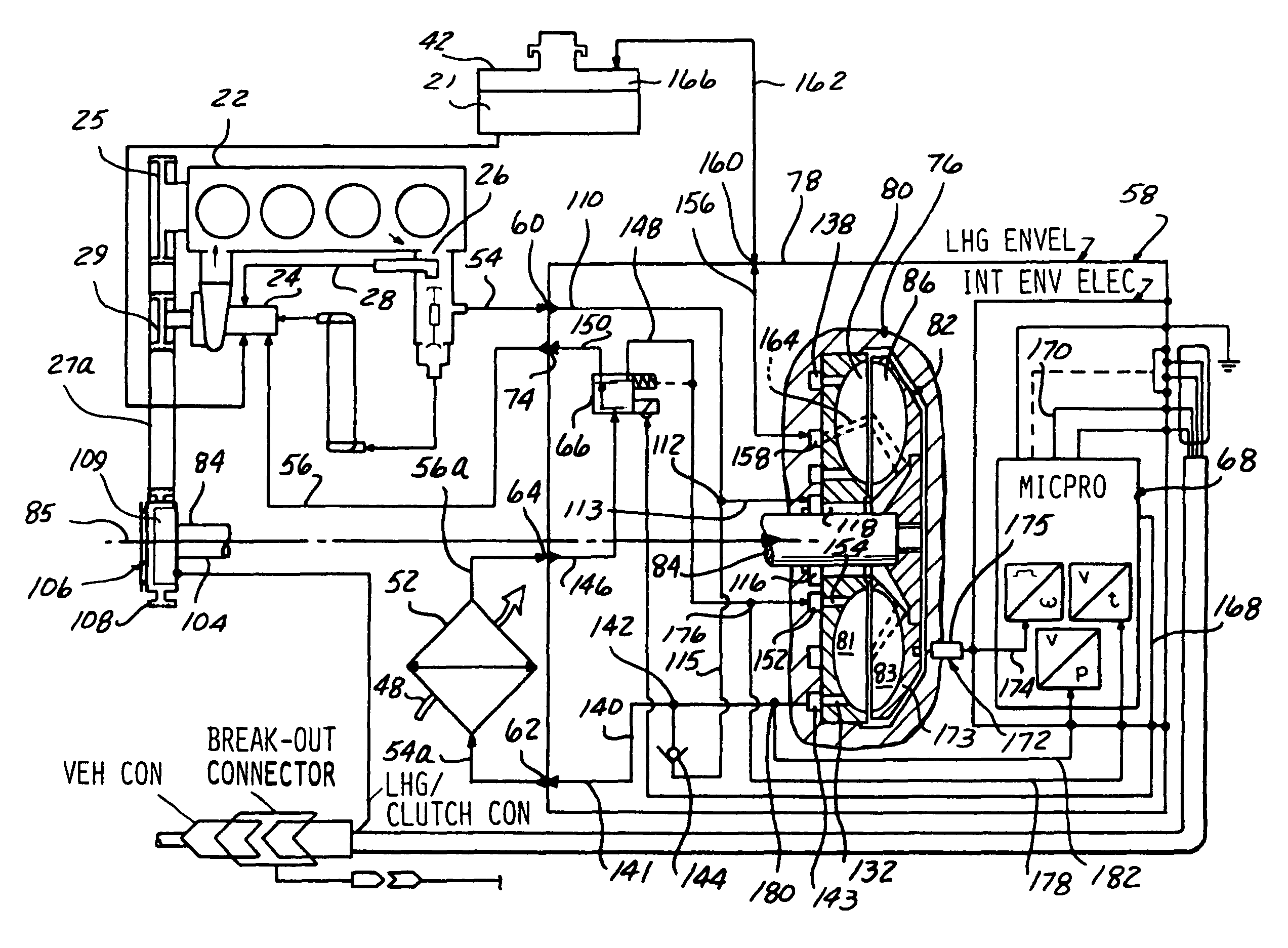
The present invention is a supplemental heating system for vehicles that improves the efficiency of heating the passenger compartment. It uses a liquid heat generator to provide additional heat to the cooling system of the engine, which in turn warms up the air flowing through the heating system. This system addresses the delay in providing heat to the passenger compart when the engine is first started and ensures that the temperature of the air is at an acceptable level as quickly as possible. The invention also addresses the potential limitation of using the engine cooling fluid as a heat source by developing a supplemental heating system that can intermittently provide additional heating to the cooling fluid.

Problems solved by technology

One disadvantage of using the engine cooling fluid as a heat source, however, is that there is typically a significant delay between when the vehicle's engine is first started and when the heating system begins supplying air at a preferred temperature.
This is particularly true when the vehicle is operated in very cold ambient conditions or has sat idle for a period of time.
The delay is due to the cooling fluid being at substantially the same temperature as the air flowing through the heating system and into the passenger compartment when the engine is first started.
Another potential limitation of using the engine cooling fluid as a heat source for the vehicle's heating system is that under certain operating conditions the engine may not be rejecting enough heat to the cooling fluid to enable the air stream from the vehicle's heating system to achieve a desired temperature.
This results in less heat energy available for heating the air flowing through the vehicle's heating system.

Method used


Image

  • Vehicle supplemental heating system
  • Vehicle supplemental heating system
  • Vehicle supplemental heating system

Examples


Embodiment Construction

[0018]The following description of the preferred embodiments is merely exemplary in nature and is in no way intended to limit the invention, its application, or uses.

[0019]Referring to FIG. 1, a schematic of a conventional vehicle cooling system 20 for regulating the operating temperature of an engine 22 is shown. Cooling system 20 includes a water pump 24 that is operable to circulate a cooling fluid 21 through engine 22 to absorb excess heat produced by engine 22. The excess heat is a byproduct of combusting a mixture of fuel and air in cylinders 23 of engine 22 to produce usable mechanical work for propelling the vehicle. Water pump 24 may be powered by an engine accessory drive 25 by means of drive belt 27 that engages a sheave 29 of water pump 24. Accessory drive 25 is typically connected to a crankshaft (not shown) of engine 22. The cooling fluid is circulated through passages (not shown) in the engine where the fluid absorbs some of the excess heat. After circulating through ...


PUM


Abstract

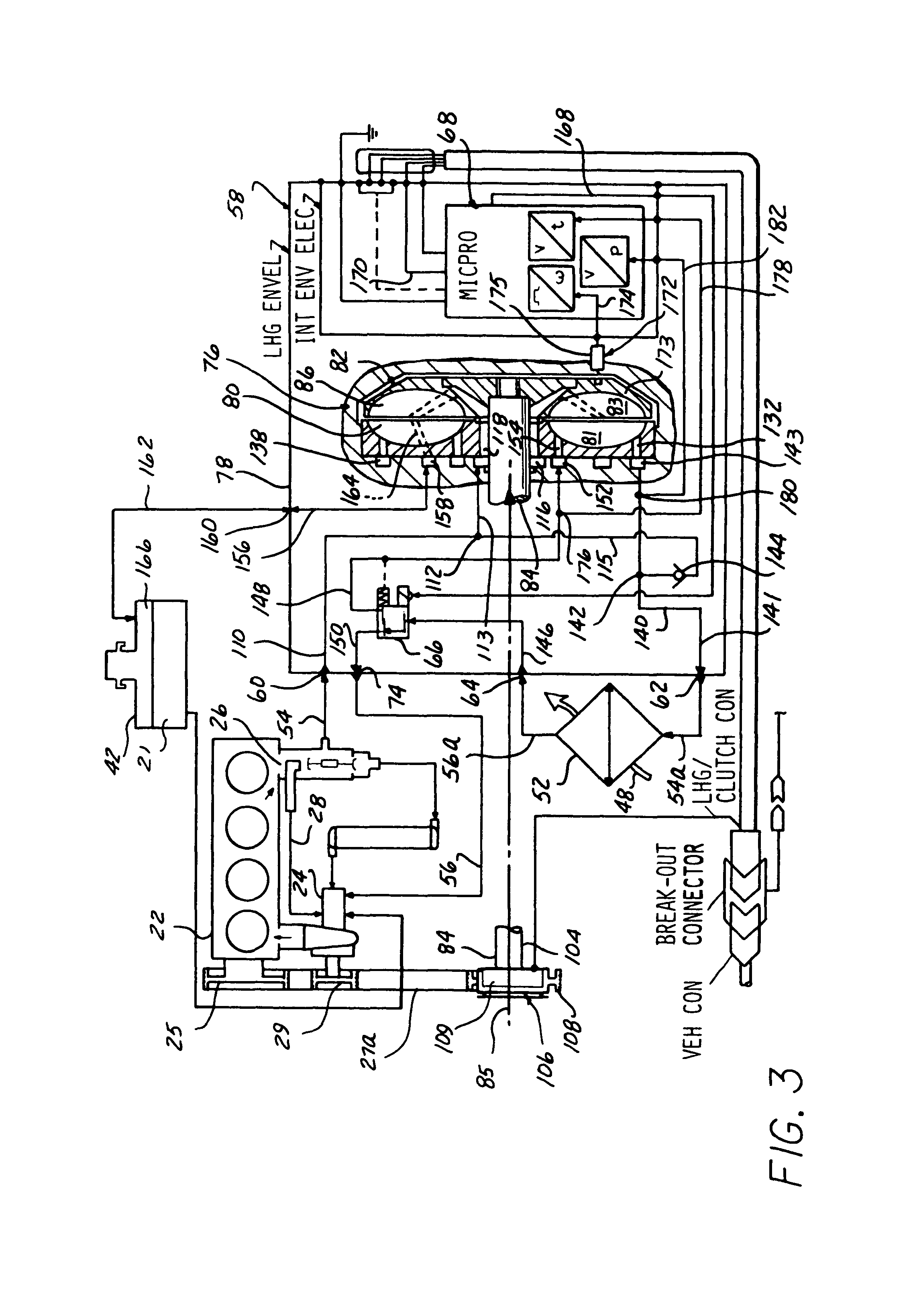
A preferred embodiment supplemental heating system is fluidly connectable to a vehicle cooling system and includes a liquid heat generator operable for heating a cooling fluid delivered to the supplemental heating system from the vehicle's cooling system. The liquid heat generator includes a discharge passage connectable to a heater core of the vehicle and a inlet passage connectable to the vehicle's cooling system. The supplemental heating system further includes a control valve having an inlet connectable to an exit passage of a heater core of the vehicle, a discharge passage fluidly connected to the liquid heat generator, and a second discharge passage connectable to the vehicle's cooling system. The control valve is operable for controlling the proportion of cooling fluid exiting the heater core that is returned to the vehicle's cooling system and recirculated back to the liquid heat generator.

Description

RELATED APPLICATIONS[0001]This application is a continuation of U.S. Provisional Application Ser. No. 60 / 547,814 filed Feb. 26, 2004.FIELD OF THE INVENTION[0002]The present invention relates in general to heat generators, and more particularly, to a supplemental liquid heating system for providing supplemental heat to a passenger compartment of an automotive vehicle.BACKGROUND OF THE INVENTION[0003]Conventional automotive vehicles typically include a heating system for supplying warm air to a passenger compartment of the vehicle. The heating system includes a control system that allows a vehicle operator to regulate the quantity and / or temperature of air delivered to the passenger compartment so as to achieve a desirable air temperature within the passenger compartment. Cooling fluid from the vehicle's engine cooling system is commonly used as a source of heat for heating the air delivered to the passenger compartment.[0004]The heating system typically includes a heat exchanger flui...

Claims


Application Information

Patent Timeline
Patent Type & Authority Patents(United States)
IPC IPC(8): F24J3/00B60H1/02B60H1/22B60H1/00B60H1/03F24D1/00
CPCB60H1/00314B60H1/038F24J3/003F01P2060/08F01P2060/06F24V40/00B60H1/00807B60H1/00878
Inventor SANGER, JEREMY J.GARAVOGLIA, FRANCO
Owner WEBASTO AG
Learn More