
Surface covering installation tool and method

a technology for installing tools and surfaces, applied in the field of surface covering installation tools and methods, can solve the problems of high inefficiency and inherent health risks of current methods of installation, roll typically drifts off the target covering area, and becomes uneven and slack, and the kick method provides little control of the rolled surface covering. , to achieve the effect of reducing the installation time and efficient control

Inactive Publication Date: 2012-10-30
GLOBAL EXPERIENCE SPECIALISTS
View PDF11 Cites 0 Cited by
  • Summary
  • Abstract
  • Description
  • Claims
  • Application Information

AI Technical Summary

Benefits of technology

The tool significantly reduces installation time and minimizes the risk of injuries by providing efficient and controlled unrolling of surface coverings, thereby decreasing workman's compensation premiums and operational costs.

Problems solved by technology

Current methods of installation are highly inefficient and possess inherent health risks.
As each worker kicks the roll forward, the roll typically drifts off the target covering area and becomes uneven and slack.
The kick method provides little control of the rolled surface covering.
Secondary operations result in increased inefficiencies and increased likelihood of injury.
Also, the repetitive movement and stress on the lower body while performing the kick method causes an increased likelihood of lower body injuries.
This results in the roll rolling off the dolly shelf and moving forward a few inches.
This method is inefficient because the dolly only moves the roll forward a very small distance each step.
Using this method increase installation time consequently increasing costs.
This method is slow and forces workers to work from an awkward position, increasing the risk of injury to the workers.
These methods of rolling out floor covering causes back, knee, and muscle injuries.
The frequency of these injuries is exacerbated by the scale of large installation projects and the minimal time allotted to accomplish the installation.
Because of installation time constraints, workers are only given a narrow window of time to install floor coverings.
The redundancy of the awkward labor causes the workers numerous injuries.
Further costs are added due to extreme inefficiencies based on the two to two-and-a-half minute time requirements for unrolling each of the floor coverings.
The added inefficiency of accomplishing the secondary operations of straightening and taping the surface coverings adds even more costs.

Method used


Image

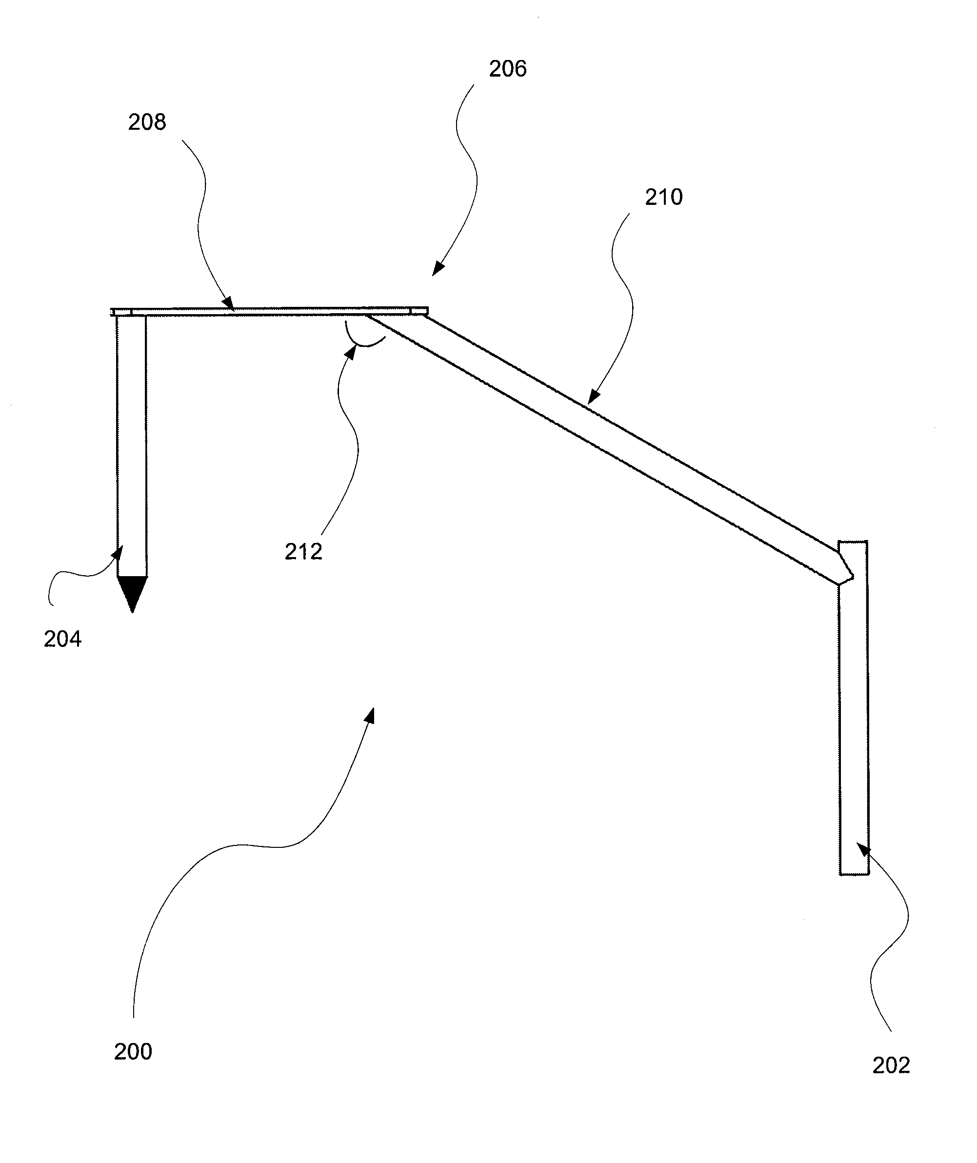
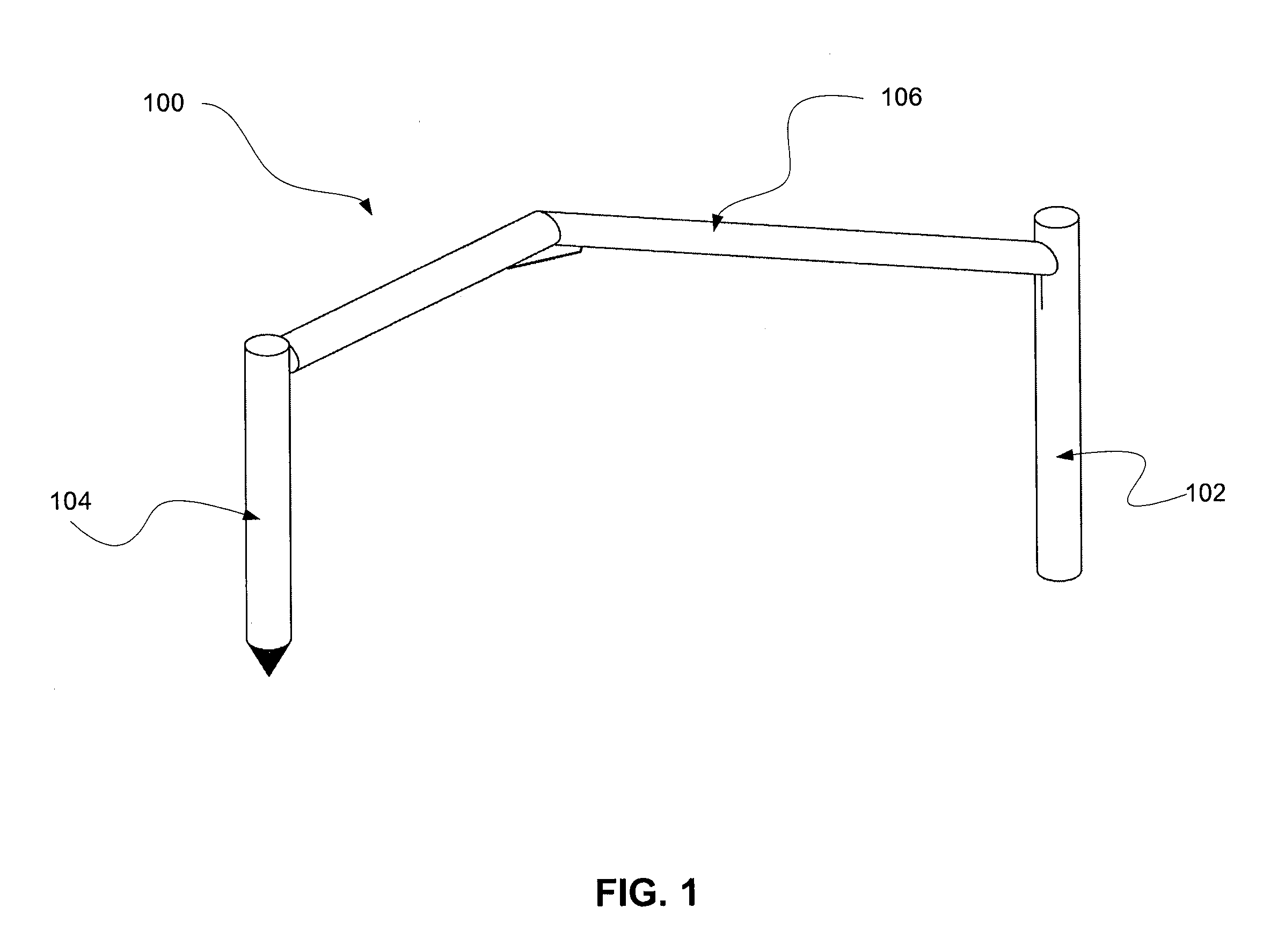
  • Surface covering installation tool and method
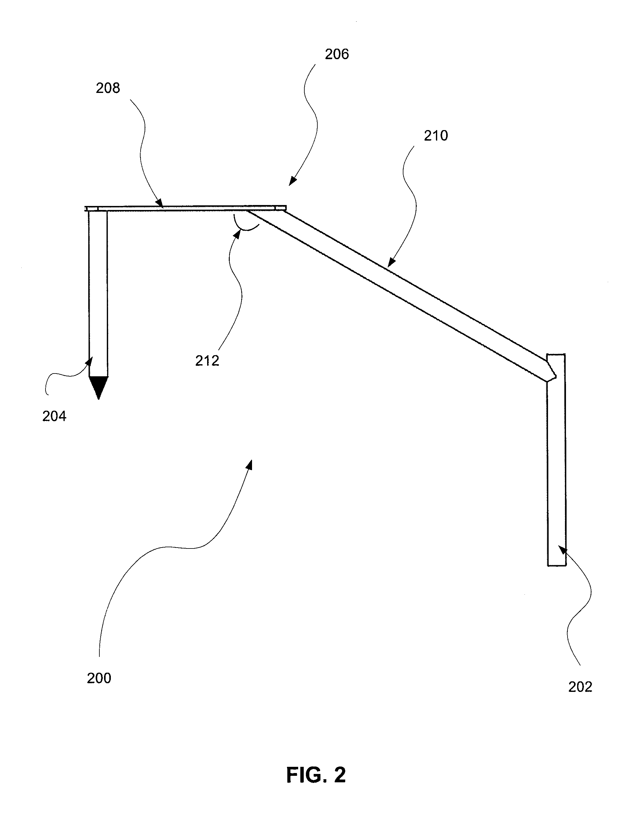
  • Surface covering installation tool and method
  • Surface covering installation tool and method

Examples


Embodiment Construction

[0014]The detailed description of exemplary embodiments of the invention herein shows the exemplary embodiment by way of illustration and diagrams including the best mode. While these exemplary embodiments are described in sufficient detail to enable those skilled in the art to practice the invention, it should be understood that other embodiments may be realized and that logical and mechanical changes may be made without departing from the spirit and scope of the invention. Thus, the detailed description herein is presented for purposes of illustration only and not of limitation. For example, the steps recited in any of the method or process descriptions may be executed in any order and are not limited to the order presented.

[0015]Moreover, for the sake of brevity, certain sub-components of individual components and other aspects of the system may not be described in detail herein. Furthermore, the connecting lines shown in the various figures contained herein are intended to repre...


PUM


Abstract

A surface covering installation tool and method of use to provide improved safety and efficiency for surface covering installation. The surface covering installation tool is a tool that includes a handle, a mandrel, and a support member. A user inserts the mandrel into rolled surface covering and then pulls the rolled surfaced covering using the handle causing the surface covering to unroll.

Description

CROSS-REFERENCE TO RELATED APPLICATIONS[0001]This application claims priority to U.S. Provisional Application Ser. No. 61 / 147,670, filed on Jan. 27, 2009 and entitled “SURFACE COVERING TOOL,” which is incorporated herein by reference in its entirety.FIELD OF INVENTION[0002]This invention generally relates to a tool and method used to unroll surface covering material.BACKGROUND OF THE INVENTION[0003]There are numerous surface covering materials on the market today used in numerous industries. Some surface covering materials arrive from the manufacture, distributor, or storage warehouse as rolls of the material. A non exclusive list of examples might include carpets, mats, padding, linoleum, or certain roofing material. Various industries require mass installation of these surface coverings. Current methods of installation are highly inefficient and possess inherent health risks.[0004]The current and perhaps most common method for a worker to roll out floor covering is the kick method...

Claims


Application Information

Patent Timeline
Patent Type & Authority Patents(United States)
IPC IPC(8): B65H16/00
CPCA47G27/0487
Inventor LAUREL, MARTINIZZO, LEONARD
Owner GLOBAL EXPERIENCE SPECIALISTS
Learn More