
Outdoor oven and cooking system

a technology for outdoor ovens and cooking systems, which is applied in the field of outdoor ovens, can solve the problems of inefficient heat use, high thermal resistance of grills manufactured from aluminum, and inability to efficiently use heat, so as to prevent heat loss, inhibit heat loss, and minimize heat loss to the environment

Inactive Publication Date: 2012-10-23
DYNAMIC ENG DESIGNS
View PDF51 Cites 33 Cited by
  • Summary
  • Abstract
  • Description
  • Claims
  • Application Information

AI Technical Summary

Benefits of technology

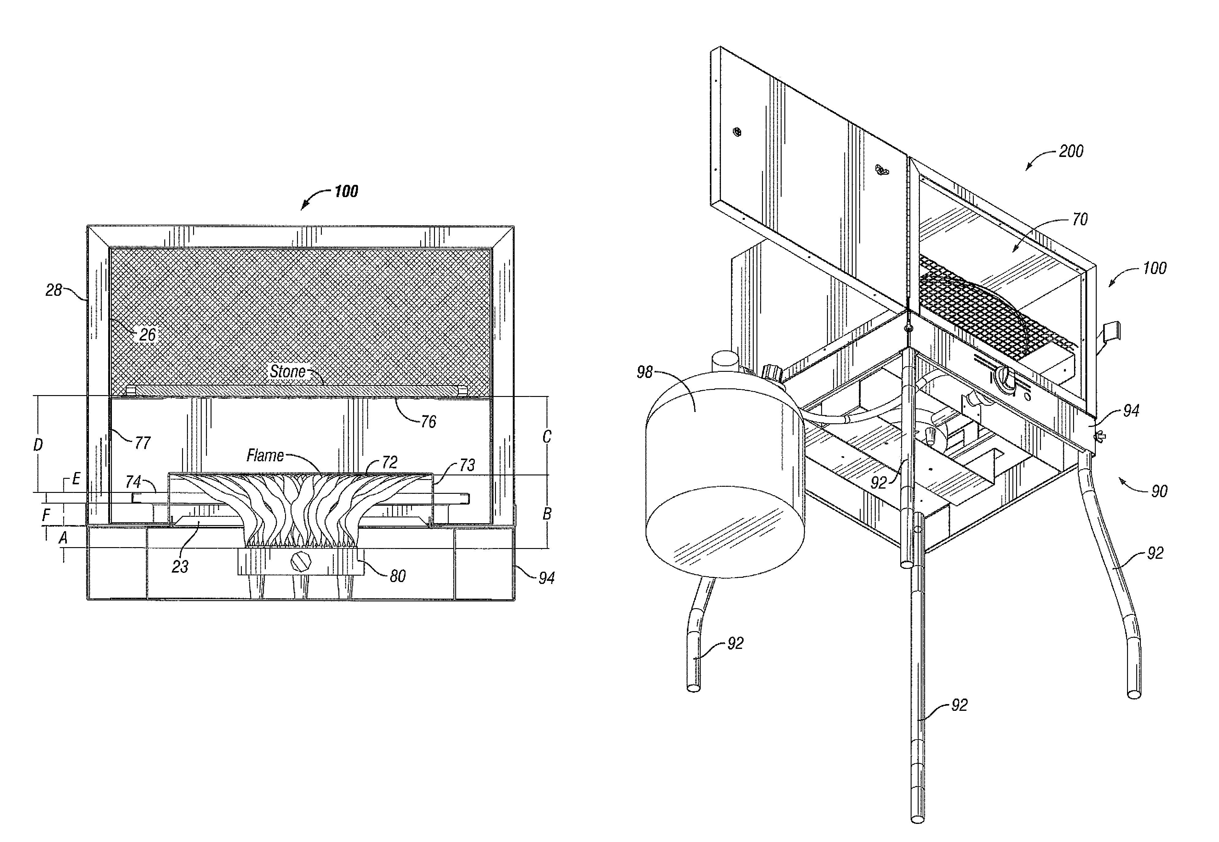
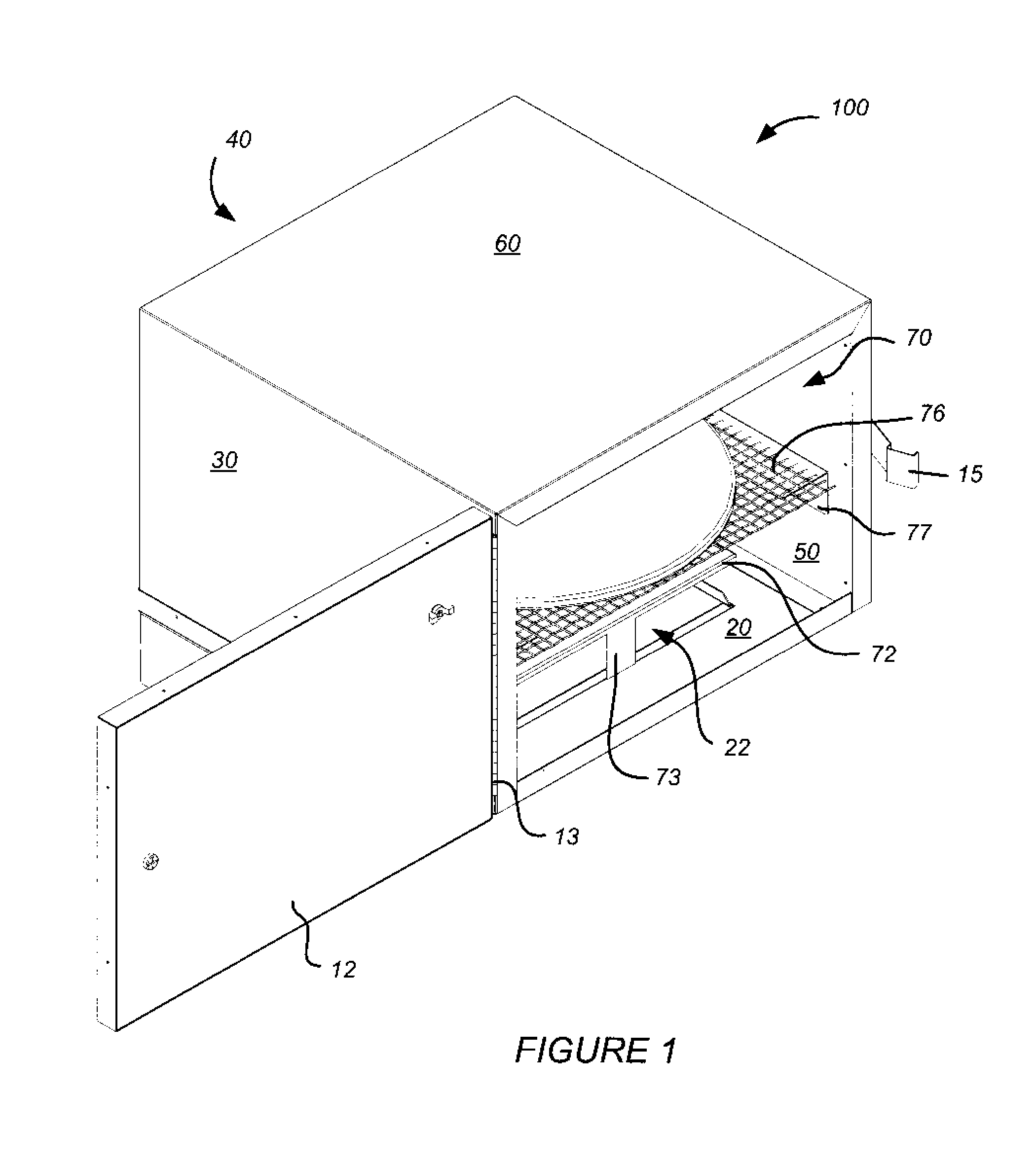
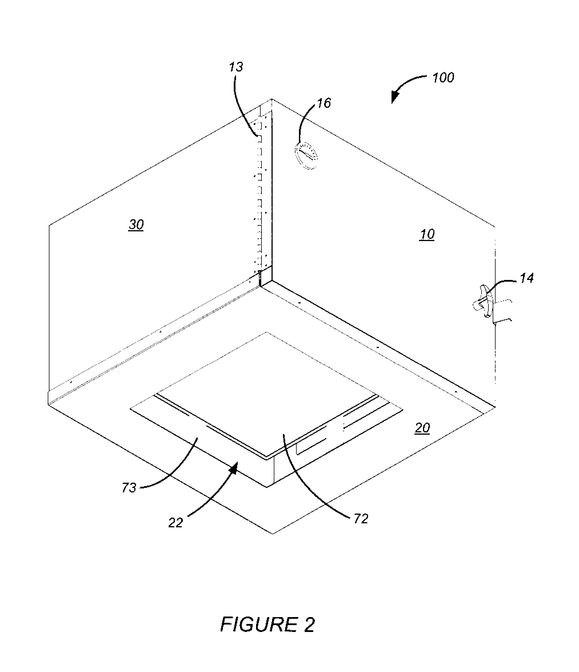
[0009]An outdoor oven may be insulated to prevent heat loss. An outdoor oven may utilize double wall insulated sides and an insulated door to inhibit heat loss. An outdoor oven may heat foods to a desired temperature with minimal heat loss to the environment. An outdoor oven may prevent heat from being in direct contact with food in the cooking chamber. An outdoor oven may circulate heat through the cooking chamber for even cooking. An outdoor oven may have one or more vents positioned below a cooking plane for directing the flow of heated air circulating through the cooking chamber.

Problems solved by technology

A disadvantage with some prior art cooking devices is that they are uninsulated or poorly insulated, resulting in the inefficient use of heat.
As a result, a grill manufactured from aluminum may dissipate heat through the casing.
A wall constructed of a material with high thermal resistance but having openings for heat to escape and having hinges, fittings, or other features with low thermal resistance to allow heat to escape may be poorly insulated.
The inefficient use of heat limits the quality of food that can be cooked on the cooking device.
Hot spots, burned food, undercooked food, dried out food and the like are possible when using a cooking device that has inefficient use of fuel.

Method used


Image

  • Outdoor oven and cooking system
  • Outdoor oven and cooking system
  • Outdoor oven and cooking system

Examples


Embodiment Construction

[0025]The inventive outdoor oven and cooking system and the various features and advantageous details thereof are explained more fully with reference to the non-limiting embodiments detailed in the following description. Descriptions of well known starting materials, manufacturing techniques, components and equipment are omitted so as not to unnecessarily obscure the disclosure in detail. Skilled artisans should understand, however, that the detailed description and the specific examples, while disclosing preferred embodiments of the disclosure, are given by way of illustration only and not by way of limitation. Various substitutions, modifications, and additions within the scope of the underlying inventive concept(s) will become apparent to those skilled in the art after reading this disclosure. Skilled artisans can also appreciate that the drawings disclosed herein are not necessarily drawn to scale.

[0026]As used herein, the terms “comprises,”“comprising,” includes, “including,”“h...


PUM


Abstract

An outdoor oven may have a cooking chamber defined by six sides. Each of the six sides may be insulated. A front side may have a door for access to the cooking chamber. The cooking chamber may have a baffle and a cooking plane above and separated some distance from the baffle. Heat in the form of a flame may enter the cooking chamber. The baffle may prevent heat from the flame from directly contacting food on the cooking plane, may inhibit heat transfer through the baffle, and / or may direct heated air around the baffle. The heat is circulated through the cooking chamber to heat the food, and exits a vent positioned below the cooking chamber. An outdoor cooking system may include a burner, a support structure and a fuel supply.

Description

CROSS-REFERENCE TO RELATED APPLICATIONS[0001]This application claims priority from Provisional Patent Applications No. 60 / 958,665, filed Jul. 6, 2007, entitled “PORTABLE COOKING SYSTEM, APPARATUS AND METHOD” and No. 60 / 974,698, filed Sep. 24, 2007, entitled “PORTABLE COOKING SYSTEM, APPARATUS AND METHOD,” the entire contents of which are expressly incorporated herein by reference for all purposes.BACKGROUND[0002]1. Field of the Disclosure[0003]The present disclosure generally relates to outdoor ovens. Embodiments of the disclosure relate to ovens, apparatuses and systems for cooking outdoors.[0004]2. Description of Related Art[0005]Outdoor cooking is desirable for camping, tailgating, and other outdoor activities. Outdoor cooking devices such as grills are generally manufactured from cast aluminum to reduce manufacturing costs or to minimize weight. Access to food being cooked is either by a door on the front of the outdoor cooking device or a lid lowered over the device. Food may b...

Claims


Application Information

Patent Timeline
IPC IPC(8): F24C3/00F24C15/30F24C15/32F24C3/02F24C15/34F24C3/08F24C15/16F24C15/08F24C15/00F24C3/14
CPCA47J37/0647F24C3/14F24C3/067
Inventor GONNELLA, GEORGE L.GONNELLA, ROBERT H.GASHGAEE, IRAJ
Owner DYNAMIC ENG DESIGNS
Learn More