
Remote sensing of subsurface artifacts by use of visual and thermal imagery

a technology of thermal imagery and subsurface artifacts, applied in the direction of material flaw investigation, optical radiation measurement, instruments, etc., can solve the problems of not having “as-built” engineering drawings or mapping information, and saving enormous money and manpower costs

Inactive Publication Date: 2012-10-16
WEIL GARY J
View PDF6 Cites 4 Cited by
  • Summary
  • Abstract
  • Description
  • Claims
  • Application Information

AI Technical Summary

Benefits of technology

Enables rapid, cost-effective, and highly accurate detection and mapping of subsurface artifacts, reducing manpower and economic costs, and enhancing safety by identifying potential security threats without disrupting public activities or infrastructure.

Problems solved by technology

In almost all instances, no “as-built” engineering drawings or mapping information exists because of age, lack of funding, or purpose.
This could save enormous money and manpower costs in crime control, welfare costs, and political needs and human lives.

Method used


Image

  • Remote sensing of subsurface artifacts by use of visual and thermal imagery
  • Remote sensing of subsurface artifacts by use of visual and thermal imagery
  • Remote sensing of subsurface artifacts by use of visual and thermal imagery

Examples


Embodiment Construction

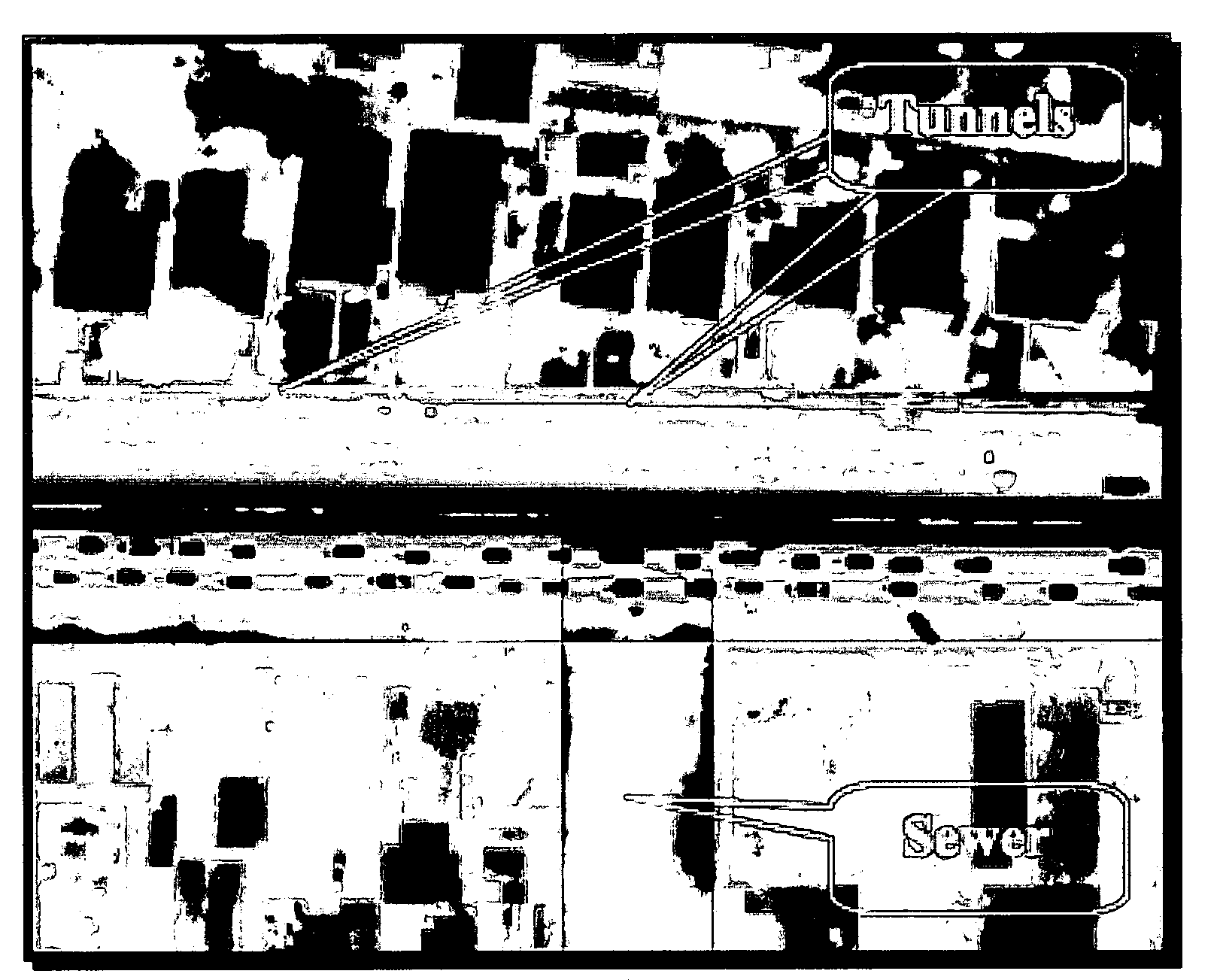
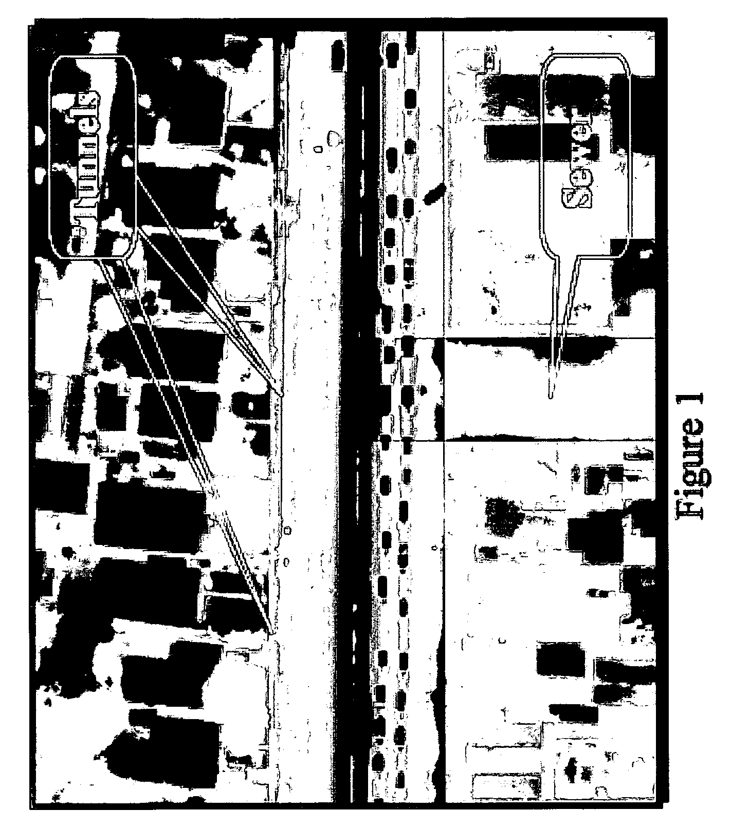
[0022]Specifically, the new remote sensing, non-invasive system, and its apparatus and methodology, is specifically designed to locate subsurface targets including, but not limited to, tunnels, underground storage tanks (USTs), clandestine storage areas and other underground / subterranean facilities where there may be munitions or material of war or crime, including drugs, weapons, munitions, and such facilities may include large pipes such as sewer, water, chemical, oil and gas, capable of allowing human traffic.

[0023]The inventive system can be configured to be hand carried, mounted on a van or truck, or mounted beneath an aerial platform either manned rotary wing, fixed wing or Unmanned Aerial Vehicle UAV) of any of various types. The various hardware mounting platforms provide users with capability to investigate small, medium and large size areas, both inside buildings and outside buildings, during both daylight and nighttime hours.

[0024]The hardware apparatus of the new system ...


PUM


Abstract

Methodology, systems, and apparatus for remote sensing as by detection and mapping of subsurface artifacts including clandestine tunnels and other subterranean facilities that may carry enemy soldiers, terrorists, weapons, munitions and explosives and other material of war or terrorism by use of visual and thermal imagery, specifically including the use of infrared (IR) thermography and related analysis, including visual imagery and its analysis including correlation between IR thermography data, visual data and other information which can be taken into consideration in relation to IR thermography data and visual data. Various types of data enhancements may be used to assist in target detection.

Description

CROSS-REFERENCE TO RELATED APPLICATION(S)[0001]This application claims the priority of U.S. Provisional Patent Provisional 60 / 875,787 filed Dec. 19, 2006, of the present inventor, Gary J. Weil, P.E., C.P.I.M., entitled REMOTE SENSING OF SUBSURFACE ARTIFACTS BY USE OF VISUAL AND THERMAL IMAGERY, the entirety of which is herein incorporated by reference.BACKGROUND AND SUMMARY[0002]1. Field of the Invention[0003]The invention relates to sensing of subsurface artifacts by use of visual and thermal imagery and more particularly to remote sensing of such subsurface artifacts as may be exemplified by tunnels and excavations.[0004]2. Related Art[0005]Methods and systems for detection of subterranean anomalies such as voids and leaks by the use of infrared thermography and, more particularly, to methods and system for using infrared thermography together with ground penetrating radar to map subterranean leakage voids and to repair such voids and terminate such leakage are the subject of U.S....

Claims


Application Information

Patent Timeline
Patent Type & Authority Patents(United States)
IPC IPC(8): G01J5/02
CPCG01N25/72G01V9/005
Inventor WEIL, GARY J.
Owner WEIL GARY J
Learn More