
Locking optical and/or electrical connectors and cable assemblies

a technology of optical and/or electrical connectors and cable assemblies, applied in the direction of coupling device connections, instruments, optical elements, etc., can solve the problems of false alarms or emergency situations, technicians often make mistakes in locating the proper duplex connector to disconnect, and achieve the effect of reducing the likelihood of accidental disconnect, more reliable and secure network

Active Publication Date: 2012-10-16
COMMSCOPE INC
View PDF29 Cites 19 Cited by
  • Summary
  • Abstract
  • Description
  • Claims
  • Application Information

AI Technical Summary

Benefits of technology

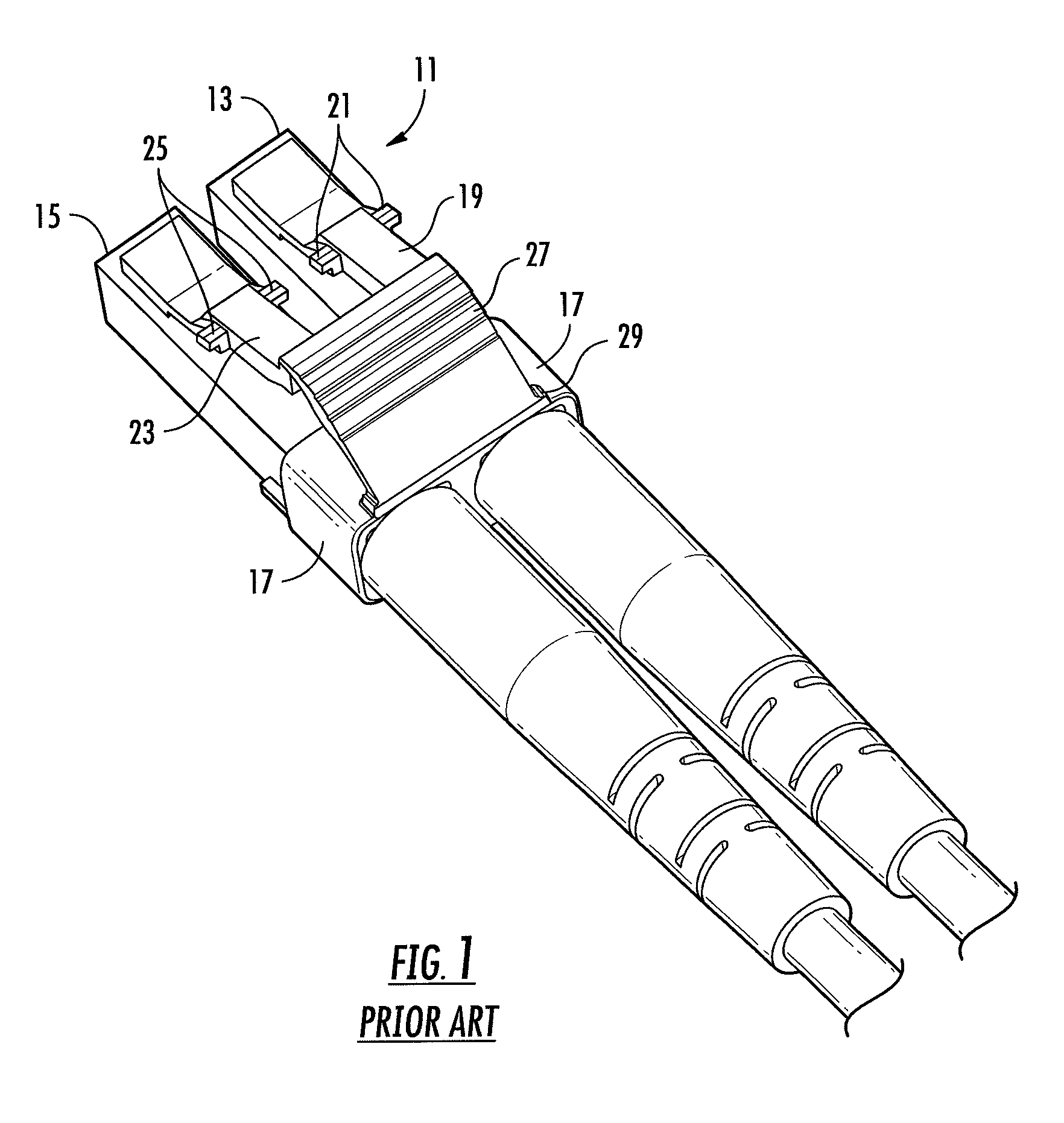
[0010]The structure of the hood 10 in U.S. Pat. No. 7,632,125 adds height / thickness to the duplex connector. Often, receptacles for duplex connectors are placed in confined or restricted places, e.g. closely adjacent to a protruding edge of a housing in the case of receptacles formed as ports on a piece of equipment's back wall; or just beneath the receptacles of another duplex connector in the case of a high density patch panel. The hood 10, as it protrudes above the duplex connector, can interfere with an adjacent structure, e.g., abut another feature on the back wall of the equipment and prevent mating of the duplex connector into the receptacles, or partially cover adjacent upper receptacles in the case of a high density patch panel, hence preventing use of the upper adjacent receptacles.
[0014]It is an object of the present invention to reduce the likelihood of accidental and intentional decoupling of communications cables resulting in a more reliable and secure network.
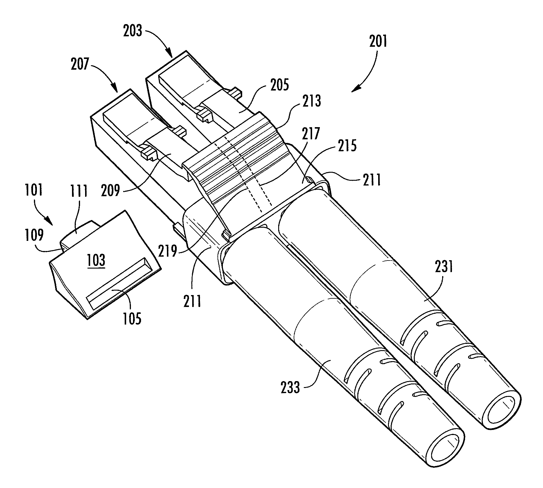
[0015]The Applicants have appreciated a need in the art for a relatively simple blocking member to be installed beneath a trigger or triggers of a fiber optic or copper duplex connector. The blocking member does not block actuation of the latches of the duplex connector. Rather, the blocking member prevents depression of the trigger(s) of the duplex connector, which normally is / are used to actuate the latches and release the duplex connector from receptacles. In a preferred embodiment, the blocking member does not add to the overall height / thickness of the duplex connector. Through the use of a simple tool the trigger(s) may be bypassed and the latches operated directly by the tool to release the duplex connector when mated to receptacles.

Problems solved by technology

Accidental disconnection can be particularly troublesome where the duplex connector is establishing essential services, which even if momentarily disconnected could lead to costly financial losses, false alarms or emergency situations, such as when an Internet connection is momentarily disconnected and Internet business transactions are interrupted or lost.
Technicians often make mistakes in locating the proper duplex connector to disconnect.
The technician may make an error in physically locating the proper patch panel and / or duplex connector corresponding to the duplex connector identified in the schematic and accidentally disconnect the wrong duplex connector.

Method used


Image

  • Locking optical and/or electrical connectors and cable assemblies
  • Locking optical and/or electrical connectors and cable assemblies
  • Locking optical and/or electrical connectors and cable assemblies

Examples


Embodiment Construction

[0040]The present invention now is described more fully hereinafter with reference to the accompanying drawings, in which embodiments of the invention are shown. This invention may, however, be embodied in many different forms and should not be construed as limited to the embodiments set forth herein; rather, these embodiments are provided so that this disclosure will be thorough and complete, and will fully convey the scope of the invention to those skilled in the art.

[0041]Like numbers refer to like elements throughout. In the figures, the thickness of certain lines, layers, components, elements or features may be exaggerated for clarity. Broken lines illustrate optional features or operations unless specified otherwise.

[0042]The terminology used herein is for the purpose of describing particular embodiments only and is not intended to be limiting of the invention. Unless otherwise defined, all terms (including technical and scientific terms) used herein have the same meaning as c...


PUM


Abstract

A blocking member is sized and shaped to be installed beneath a trigger or triggers of a duplex connector. The blocking member prevents depression of the trigger(s) of the duplex connector and hence prevents depression of latches to release the plugs of the duplex connector from mated receptacles. The blocking member does not block actuation of the latches of the duplex connector. Through the use of a tool, the trigger(s) may be bypassed and the latches operated directly by the tool to release the plugs of the duplex connector when mated to receptacles.

Description

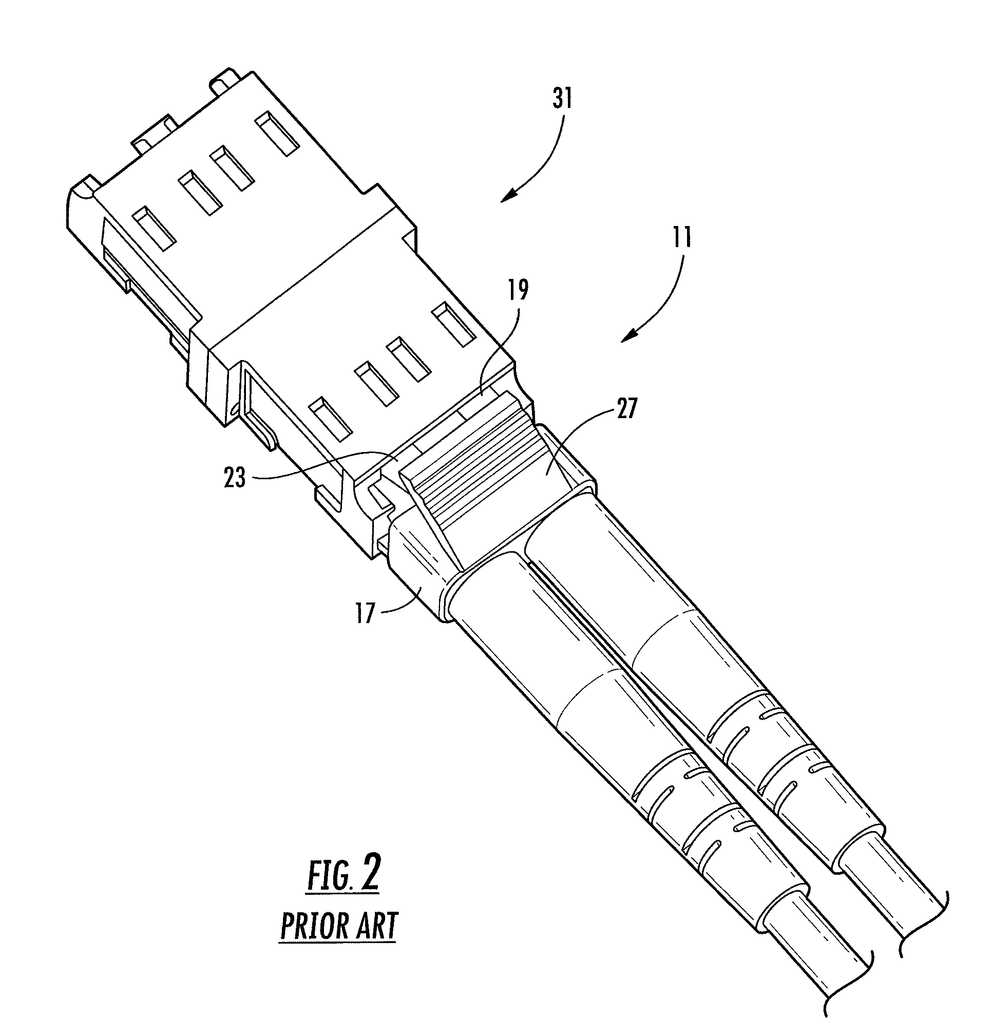
BACKGROUND OF THE INVENTION[0001]1. Field of the Invention[0002]The present invention relates to duplex connectors. More particularly, the present invention relates to a locking device to resist unlatching of tandem plugs when mated within receptacles and relates to a tool to unlatch the tandem plugs from the mated receptacles.[0003]2. Description of the Related Art[0004]FIG. 1 illustrates a duplex fiber optic connector 11 in accordance with the prior art. Generally, the duplex connector 11 includes a first plug 13 and a second plug 15, which are identically structured and which are joined together by a clip body 17. The clip body 17 may be structured to hold the first and second plugs 13 and 15 in a removable fashion, e.g., by a snap fit, or in a more permanent fashion, e.g., by an adhesive.[0005]The first plug 13 includes a flexible first latch 19. The first latch 19 includes left and right ears 21. The second plug 15 includes a flexible second latch 23 with left and right ears 25...

Claims


Application Information

Patent Timeline
Patent Type & Authority Patents(United States)
IPC IPC(8): G02B6/36
CPCG02B6/406H01R13/6273H01R13/639G02B6/3898G02B6/3879
Inventor NIELSON, JEFFREY D.BILLMAN, BRADLEY S.
Owner COMMSCOPE INC
Learn More