
User signal transmitting and receiving method, apparatus and system in OFDMA system

a user signal and access system technology, applied in the field of user signal transmitting and receiving methods and apparatuses, access systems in the smart antenna communication system of the orthogonal frequencydivision multiple access technology, can solve problems such as significant decrease in signal reception quality

Inactive Publication Date: 2012-10-09
BEIJING XINWEI TELECOM TECH
View PDF6 Cites 0 Cited by
  • Summary
  • Abstract
  • Description
  • Claims
  • Application Information

AI Technical Summary

Benefits of technology

[0095]The signal design, production and allocation method proposed by the present invention in combination with the smart antenna can reduce various interference of the receiver, greatly improve the signal reception quality, enhance the entire performance of the wireless system, and make the OFDMA system achieve particularities as follows: the sub-carrier can be flexibly arranged according to service requirements; the frequency or time selective fading can be avoided; the multi-cell interference of narrowband and broadband communication can be suppressed; the self-interference resulted from serious multi-path time delay spread can be reduced; the self-interference resulted from the circuit non-linear or phase noise occurring with the receiving / transmitting chain can be reduced; and the self-interference resulted from the Doppler spread of the mobile channel can also be reduced.

Problems solved by technology

Particularly, factors such as frequency and time selectivity of a mobile channel, frequency and time selectivity of co-frequency interference, inter-symbol and inter-carrier interference resulted from serious multi-path, interference resulted from circuit nonlinearity and phase noise may all lead to a significant decrease in the signal reception quality.

Method used


Image

  • User signal transmitting and receiving method, apparatus and system in OFDMA system
  • User signal transmitting and receiving method, apparatus and system in OFDMA system
  • User signal transmitting and receiving method, apparatus and system in OFDMA system

Examples


Embodiment Construction

[0038]Hereinafter, specific embodiments of the present invention are described in more detail with reference to the accompanying drawings.

[0039]In an OFDMA-TDMA multiplexing scheme, spectrum is divided into multiple sub-carriers, and time is divided into continuous timeslots, in which each timeslot is composed of multiple symbol periods. Therefore, in an OFDMA system, radio resources may be represented as two-dimensional time-frequency grids. In a Time Division Duplexing (TDD) system, each timeslot is configured as a downlink timeslot, an uplink timeslot or a protection timeslot. FIG. 1 shows a frame structure of a typical OFDMA-TDMA TDD system.

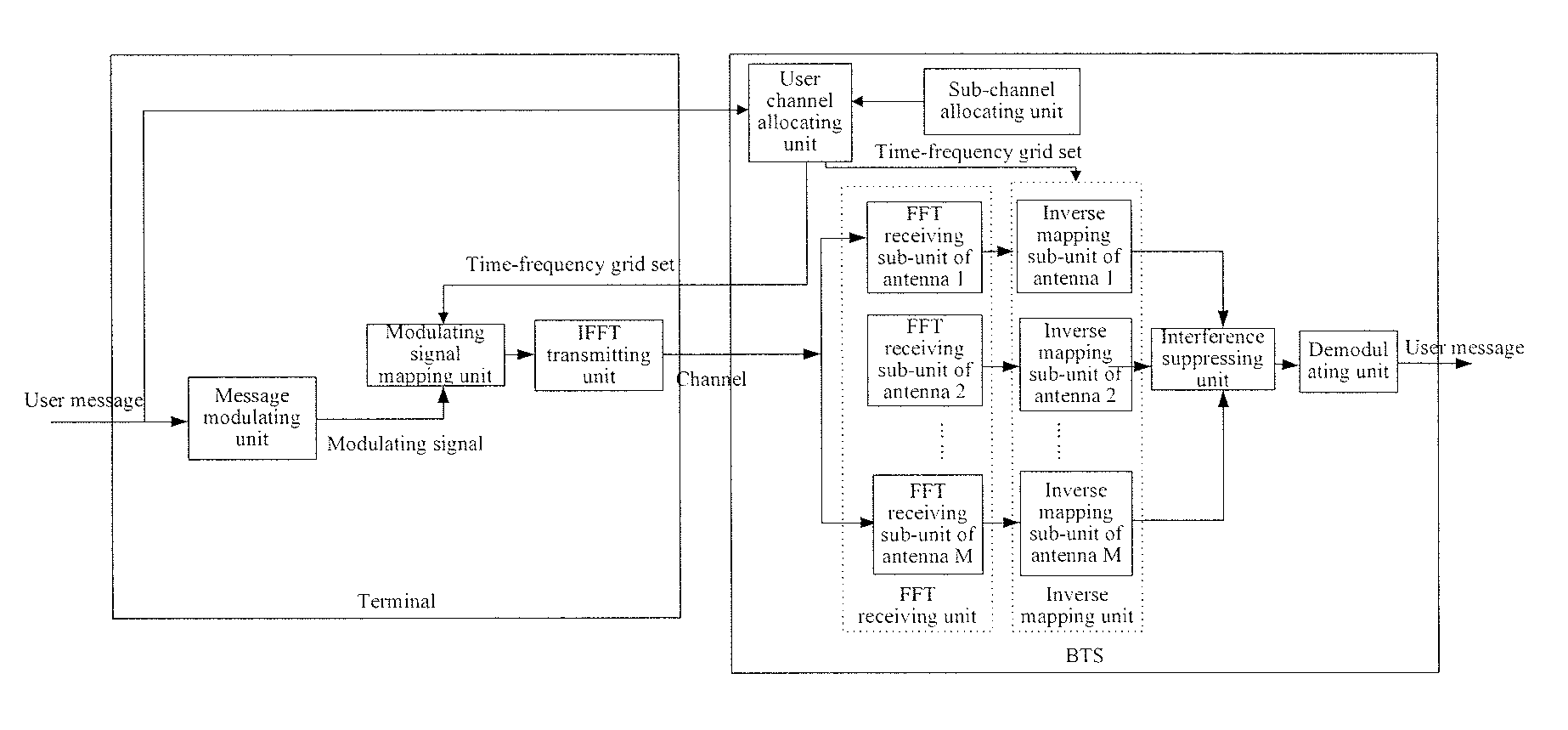
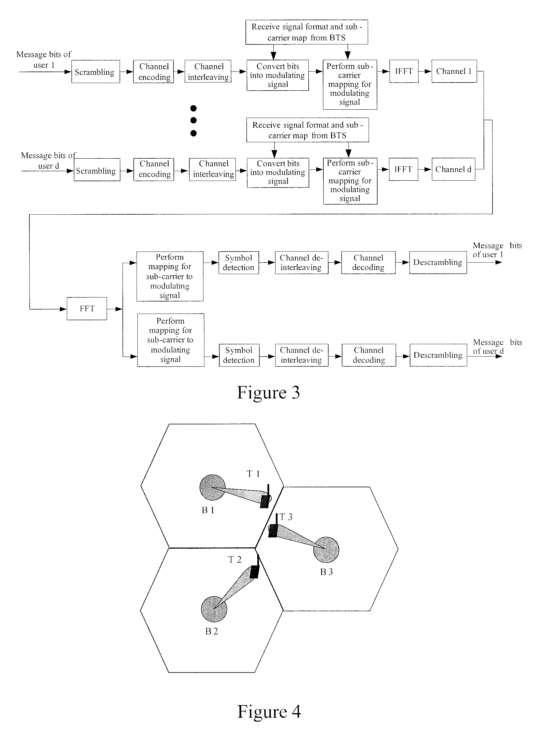
[0040]An OFDMA downlink signal is single-point-to-multipoint while an OFDMA uplink signal is multipoint-to-single-point. In FIG. 2, a downlink transmission signal is generated by mapping a modulating signal of each user to the time-frequency grids allocated to the user. According to bandwidth requirements of users, the modulating signal of th...


PUM


Abstract

This invention provides a user signal transmitting method in an OFDMA system, where all the time-frequency grids of each timeslot are divided into sub-channels, each sub-channel comprises Nf sub-carriers overlapping in time, Nf≧4, and in each sub-channel, a maximum value of a frequency interval between adjacent sub-carriers is no less than three times of a minimum value thereof; and when a user message is sent, comprising: generating a modulating signal; allocating a time-frequency grid set which is a union set of sub-channel, where the sub-channel's quantity is determined by the user message's size, and the sub-channel's time-frequency position is selected according to a rule; and mapping the modulating signal to the time-frequency grid set to generate a frequency-domain signal; performing IFFT on the frequency-domain signal to generate a time-domain signal for transmission. This invention also provides a corresponding user signal receiving method, user signal transmitting and receiving apparatus and access system.

Description

FIELD OF THE INVENTION[0001]The present invention relates to an Orthogonal Frequency-Division Multiple Access (OFDMA) technology and particularly, to a user signal transmitting method and apparatus, a user signal receiving method and apparatus, and an access system in an OFDMA smart antenna communication system.BACKGROUND OF THE INVENTION[0002]For an OFDMA wireless system supporting hybrid communication of data and voice, a narrowband user and a broadband user may access the wireless system simultaneously. Therefore, there is a need to plan a sub-carrier flexibly to adapt to service traffic variation in real time. On the other hand, a narrowband service has much higher requirements for signal reception quality. Particularly, factors such as frequency and time selectivity of a mobile channel, frequency and time selectivity of co-frequency interference, inter-symbol and inter-carrier interference resulted from serious multi-path, interference resulted from circuit nonlinearity and pha...

Claims


Application Information

Patent Timeline
Patent Type & Authority Patents(United States)
IPC IPC(8): H04J11/00
CPCH04L5/0007H04L5/0037H04L5/0064H04L27/2626H04L27/2647
Inventor LI, HANG
Owner BEIJING XINWEI TELECOM TECH
Learn More