Ferrous sintered multilayer roll-formed bushing, producing method of the same and connecting device

a multi-layer, rolling-formed bushing technology, applied in the direction of metal-working apparatus, engine components, metal-layered products, etc., can solve the problems unable to eliminate the necessity of lubricating, and unable to prevent, so as to prolong the lubrication interval. , the effect of prolonging the lubrication interval

Inactive Publication Date: 2012-10-09
KOMATSU LTD
View PDF21 Cites 7 Cited by
  • Summary
  • Abstract
  • Description
  • Claims
  • Application Information

AI Technical Summary

Benefits of technology

[0018]In a conventionally used sintered sliding material equipped on a connecting device operated under severe sliding conditions such as high bearing stress, slow speed sliding and oscillating conditions, it is impossible to prevent occurrence of abnormal noise and to prolong a lubrication interval because of its high coefficient of friction (0.15 or more) and insufficient seizing resistance and abrasion resistance. And, it is also impossible to eliminate the necessity of lubricating because of its insufficient self-lubricating ability.
[0019]Accordingly, an object of the present invention is to provide an economic ferrous sintered multilayer roll-formed bushing, a producing method of the same and a connecting device, in which a ferrous sintered sliding material layer is tightly sinter-bonded to a back metal steel, the ferrous sintered sliding material layer being intended to have low coefficient of friction, having excellent seizing resistance and abrasion resistance and providing self-lubricating property so as to prolong a lubrication interval or eliminate the necessity of lubricating.
[0066]As described above, according to the present invention, an economical ferrous sintered multilayer roll-formed bushing intended to have low coefficient of friction, having excellent seizing resistance and abrasion resistance and providing self-lubricating property so as to prolong a lubrication interval or eliminate the necessity of lubricating, a producing method of the same and a connecting device can be provided.

Problems solved by technology

In a conventionally used sintered sliding material equipped on a connecting device operated under severe sliding conditions such as high bearing stress, slow speed sliding and oscillating conditions, it is impossible to prevent occurrence of abnormal noise and to prolong a lubrication interval because of its high coefficient of friction (0.15 or more) and insufficient seizing resistance and abrasion resistance.
And, it is also impossible to eliminate the necessity of lubricating because of its insufficient self-lubricating ability.

Method used


Image

  • Ferrous sintered multilayer roll-formed bushing, producing method of the same and connecting device
  • Ferrous sintered multilayer roll-formed bushing, producing method of the same and connecting device
  • Ferrous sintered multilayer roll-formed bushing, producing method of the same and connecting device

Examples


example 1

(Experiment for Preliminary Sintering Ability of Various Ferrous Sintered Sliding Materials)

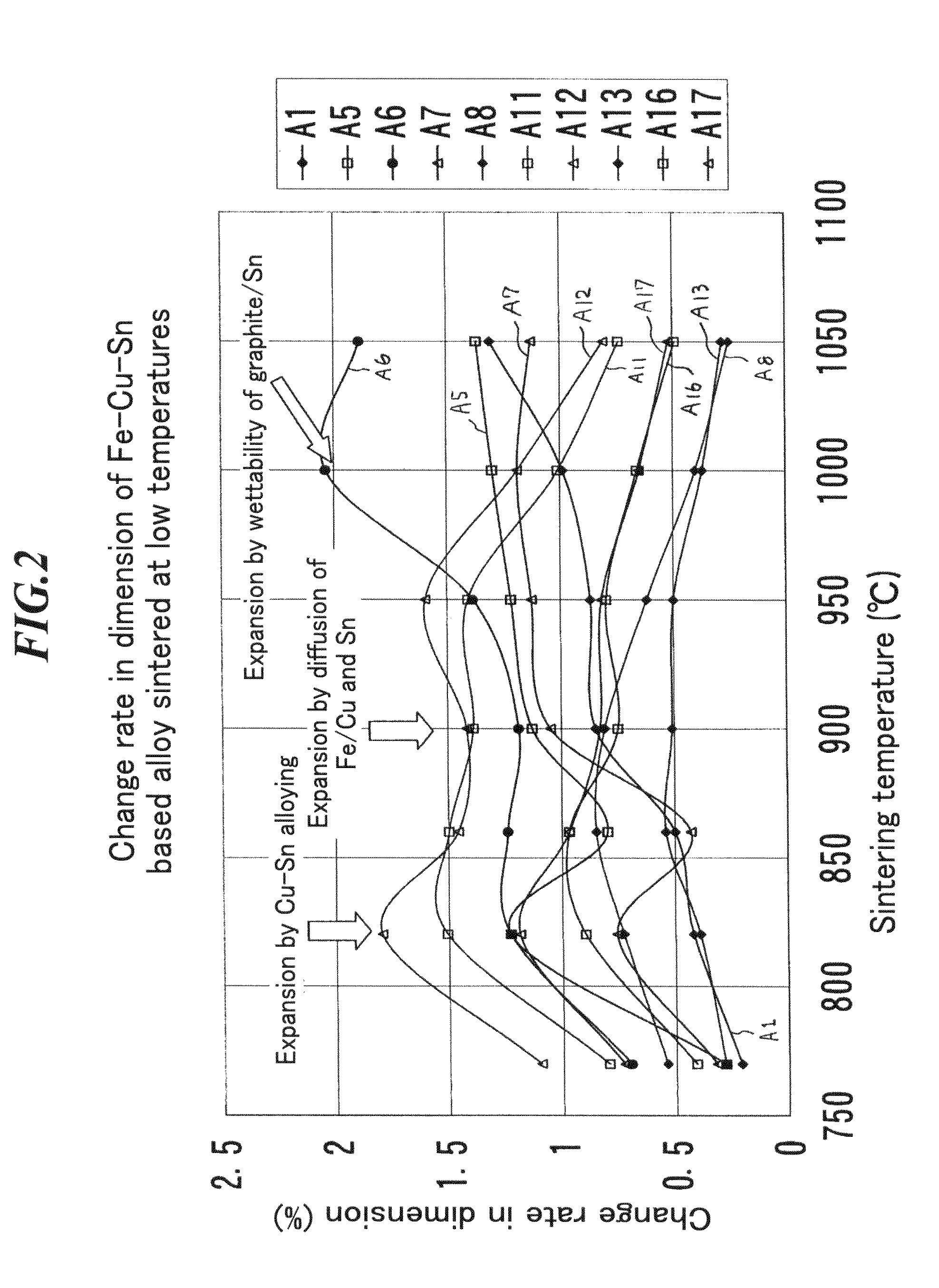
[0291]Three kinds of Cu alloy mixed powders shown in Table 1 were prepared. Ferrous sintered alloys having compositions shown in Table 3 were used in the embodiment. These sintered alloys were prepared in composition by using A300 (iron powder, manufactured by Kobe Steel, Ltd.), PX16 (high-speed steel powder Fe-1.1 wt % C-4 wt % Cr-5 wt % Mo-6 wt % W-2 wt % V, manufactured by Mitsubishi Steel Mfg. Co., Ltd.), KM15 (high Cr tool steel powder, Fe-0.45 wt % C-16 wt % Cr-3 wt % Mo-2 wt % V, manufactured by Mitsubishi Steel Mfg. Co., Ltd.), atomized copper powder of −#350 mesh or less (manufactured by FUKUDA METAL FOIL & POWDER CO., LTD.), atomized Cu-33 wt % Sn powder (manufactured by FUKUDA METAL FOIL & POWDER CO., LTD.), atomized Sn powder of −#250 mesh or less (manufactured by FUKUDA METAL FOIL & POWDER CO., LTD.) and graphite having an average grain size of 6 μm (KS6, manufactured by LONZA). ...

example 2

(Experiment for Final Sintering Ability of Various Ferrous Sintered Sliding Materials)

[0311]Tables 3-1 and 3-2 show compositions of mixed powders for ferrous sintered sliding material alloys used in the example.

[0312]Theses sliding material were prepared were prepared in composition by using ASC300 (iron powder, manufactured by Hoganas), M2 (high-speed steel powder, Fe-0.8 wt % C-4 wt % Cr-5 wt % Mo-6 wt % W-2 wt % V, manufactured by Mitsubishi Steel Mfg. Co., Ltd.), SUS440C (Fe-1.1 wt % C-17 wt % Cr, manufactured by NIPPPON ATOMIZED METAL POWDER CORRPORATION), electrolytic copper powder (CE25, manufactured by FUKUDA METAL FOIL & POWDER Co., Ltd.), TiH of −#350 mesh or smaller, electrolytic Mn, Ni, phosphor iron (25 wt % P), Mo having an average grain size of 5 μm, Fe-16 wt % Al-25 wt % Cu of #200 mesh or smaller and Fe-16 wt % Al, in addition to the powders used in Example 1. These mixed powders were formed into the test piece at a pressure of 5 ton / cm2. Each test piece was vacuum ...

example 3

(Method for Producing a Ferrous Sintered Roll-Formed Bushing 1)

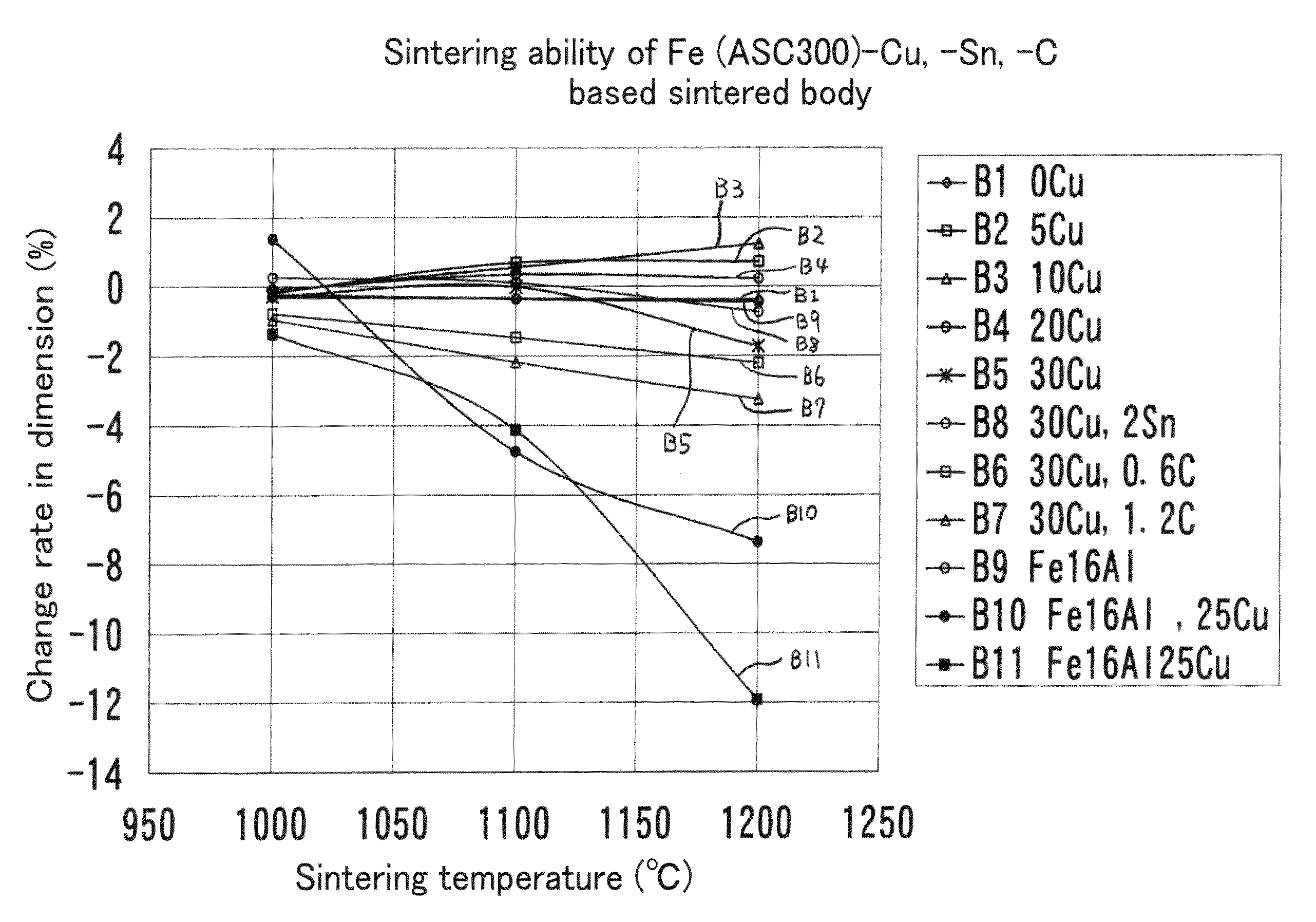
[0346]Table 4 shows compositions of alloys of ferrous sintered sliding materials used in the Example.

[0347]These sliding materials were prepared in composition by using raw material powders used in Examples 1 and 2. Each mixed powder was dispersed on a SPCC steel plate 4 mm in thickness to have a thickness of 1.4 mm. Then, after preliminary sintering at 900° C. for 15 minutes, the about 50% sintered layer was reduced by a reduction machine and then preliminarily sintered again at 900° C. for 15 minutes. After cooling, it was finally sintered at various temperatures within 1000 to 1200° C. for 30 minutes. Then, it was rapidly cooled using N2 gas of 600 torr from the sintering temperatures. The sintered body was observed and examined in sintering ability of the alloys and a lower limit of sintering temperature at which a sufficient bonding strength between each alloy and the back metal steel can be obtained.

[0348]FIGS. 18A...


PUM

PropertyMeasurementUnit
temperaturesaaaaaaaaaa
grain sizeaaaaaaaaaa
depthaaaaaaaaaa

Abstract

A ferrous sintered multilayer roll-formed bushing having a ferrous sintered sliding material layer which is sinter-bonded to a back metal steel, wherein the ferrous sintered sliding material layer is produced in such a manner that a Fe—C—Cu—Sn based sintered sliding material mixed powder containing at least carbon of 0.40 to 15 wt %, Cu of 13 to 40 wt % and Sn of 0.5 to 10 wt % is preliminarily sinter-bonded to said back metal steel and then finally sinter-bonded by a liquid-phase sintering at high temperatures higher than 1000° C. after bending into a roll.

Description

FIELD OF THE INVENTION[0001]The present invention relates to a ferrous sintered multilayer roll-formed bushing, a producing method of the same and a connecting device. More particularly, the present invention relates to a ferrous sintered multilayer roll-formed bushing intended to have low coefficient of friction, having excellent seizing resistance and abrasion resistance and providing self-lubricating property so as to prolong a lubrication interval or eliminate the necessity of lubricating, a producing method of the same and a connecting device.BACKGROUND OF THE INVENTION[0002]As a radial bearing equipped on a connecting device of a construction machine which operates under severer lubricating conditions such as high bearing stress, low-speed sliding and oscillating, a steel bearing of which at least the sliding surface is carburized or induction hardened is commonly used. Especially, in order to prevent occurrence of abnormal noise and improve seizing resistance at sliding, the ...

Claims


Application Information

Patent Timeline
Patent Type & Authority Patents(United States)
IPC IPC(8): B32B15/16F16C33/12B22F3/12B22F7/04B32B15/18
CPCB22F7/04C22C38/008C22C38/16F16C33/14F16C33/121Y10T428/12958B22F2999/00B22F2998/10Y10T428/12146Y10T29/49709B22F3/10B22F3/18B22F3/1035B22F2207/01F16C33/122F16C2220/20F16C2220/44F16C2223/04F16C2223/30F16C2226/62F16C33/12
Inventor TAKAYAMA, TAKEMORI
Owner KOMATSU LTD
Why Eureka
Try Eureka