Endoscope apparatus
a technology of endoscope and endoscope, which is applied in the field of endoscope, can solve the problems of fuel changing into gas or dust and becoming flammabl
- Summary
- Abstract
- Description
- Claims
- Application Information
AI Technical Summary
Benefits of technology
Problems solved by technology
Method used
Image
Examples
first embodiment
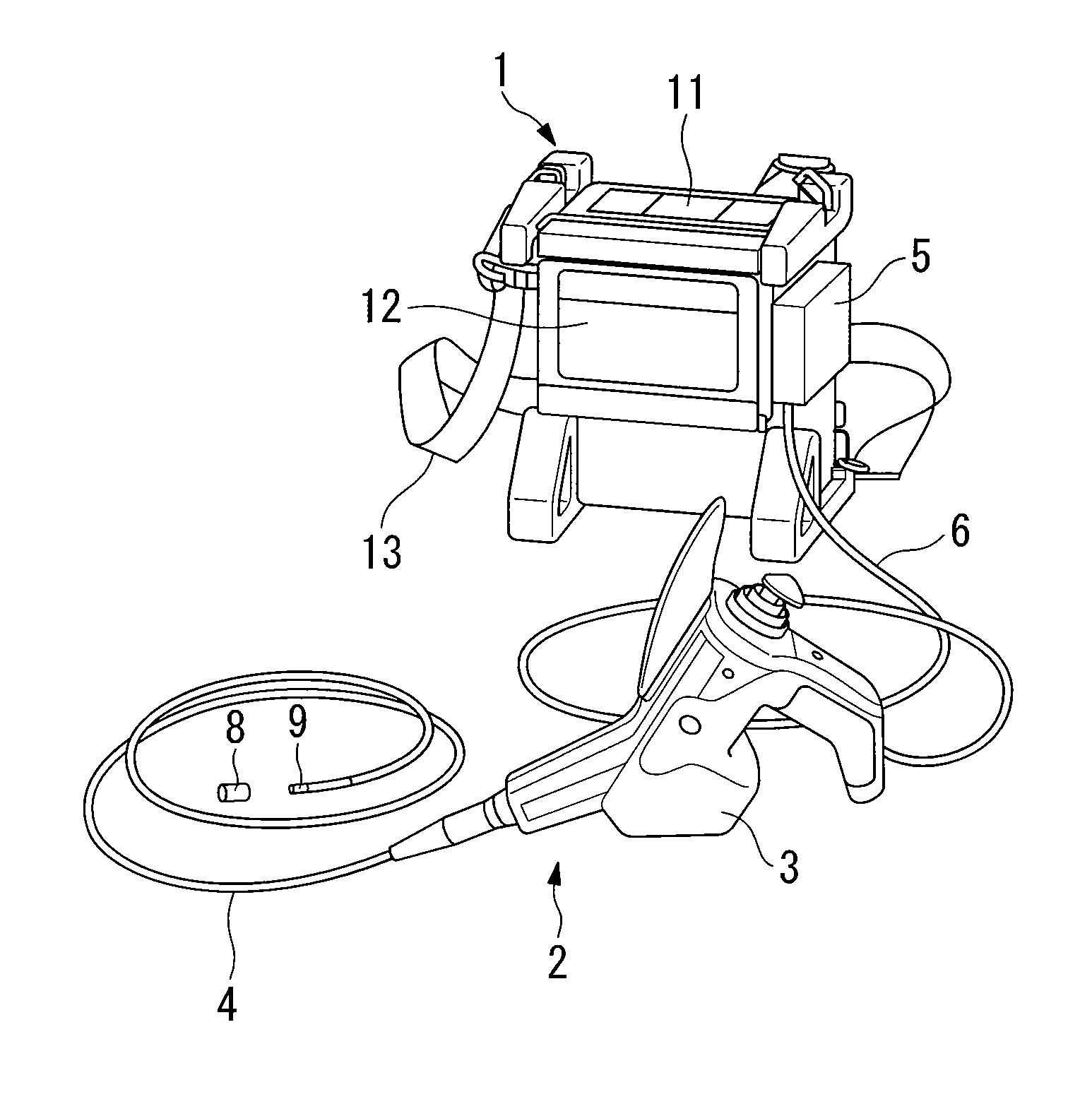
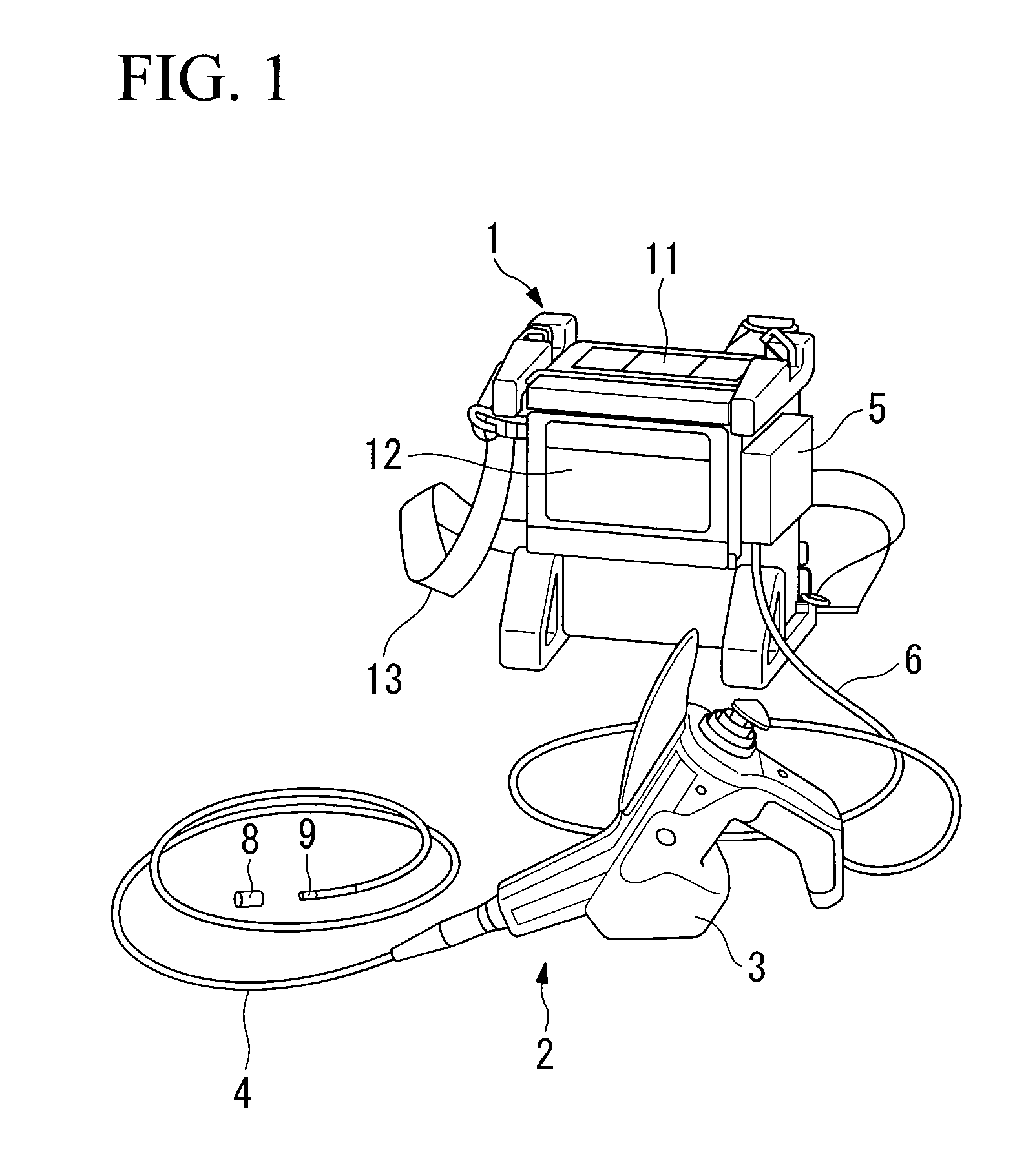
[0039]FIG. 1 is a conceptual view showing an outline of an endoscope device (i.e., an explosion-proof video image device) serving as the first embodiment of the present invention. In FIG. 1, a main unit controls the entire endoscope device. A front panel (operation panel) 11 that is used for making various settings is provided on a top surface of the main unit 1. An LCD monitor 12 that is used to display monitor images is mounted on a side surface of the main unit 1. A belt 13 can be fitted onto the main unit 1 so that a user is able to hang the main unit 1 from their shoulder and perform hands-free operation.
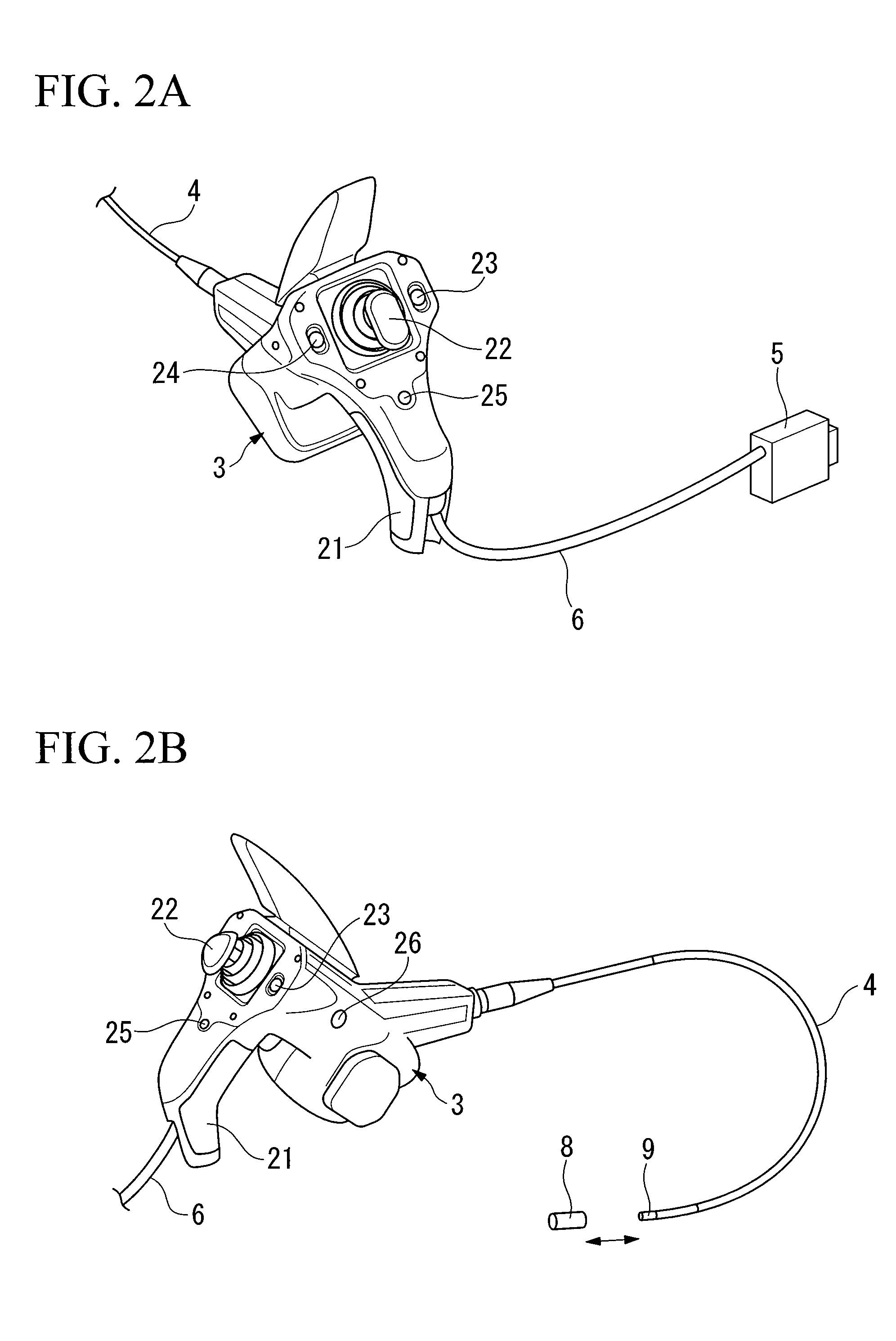
[0040]A scope unit 2 is formed by a control unit 3, an insertion portion 4 that is attached to the control unit 3, and an optical adaptor 8 that is removably attached to a distal end of the insertion portion 4. The control unit 3 is removably attached to the main unit 1 by a scope connector 5. In the first embodiment of the present invention, as described below, an energy limit...
second embodiment
[0070]The second embodiment of the present invention is an endoscope device in which the barrier circuit 45A of the first embodiment shown in FIG. 4 is replaced with the structure shown in FIG. 5. The structure of the second embodiment is the same as that of the first embodiment except for the barrier circuit 45A. As described below, by inserting a plurality of coupling condensers in each signal line, the flow of direct current between the circuits of the main unit 1 and the control unit 3 is interrupted, and the current value of the transmission current of the digital signals is limited so as to limit electrical energy in the transmission of the digital signal.
[0071]FIG. 5 shows a barrier circuit for an alternating current, however, alternating current components of digital signals starting with image data are transmitted. As shown in FIG. 5, in the barrier circuit 45A for alternating current, a structure is employed in which a condenser series (made up of a plurality of condensers...
third embodiment
[0075]The third embodiment of the present invention is an endoscope device in which the barrier circuit 45B of the first embodiment shown in FIG. 4 is replaced with the structure shown in FIG. 6. The structure of the third embodiment is the same as that of the first embodiment except for the barrier circuit 45B.
[0076]The barrier circuit 45B shown in FIG. 6 indicates an example of a barrier circuit of the type that satisfies “ib” apparatus standards, and is a barrier circuit for direct current that supplies drive power. This barrier circuit 45B is a current limiting type of overload protection circuit. When a predetermined limit current value is exceeded, the barrier circuit 45B controls the output voltage so that it equals the limit current value and thereby limits the energy.
[0077]As shown in FIG. 6, in a barrier circuit for direct current, a fuse 200 and current limiting circuits 203 and 204 that are each formed by two transistors Q1 and Q2 are inserted in series on the power supp...
PUM
 Abstract
Description
Claims
Application Information
 - R&D
- Intellectual Property
- Life Sciences
- Materials
- Tech Scout
- Unparalleled Data Quality
- Higher Quality Content
- 60% Fewer Hallucinations
Browse by: Latest US Patents, China's latest patents, Technical Efficacy Thesaurus, Application Domain, Technology Topic, Popular Technical Reports.
© 2025 PatSnap. All rights reserved.Legal|Privacy policy|Modern Slavery Act Transparency Statement|Sitemap|About US| Contact US: help@patsnap.com


