
UV camouflage system

a camouflage system and camouflage technology, applied in the field of hunting camouflage, can solve the problems of exterior water proofing of camouflage items, not providing a realistic emulation, and not accurately reflecting light in the uva spectrum of conventional camouflag

Active Publication Date: 2012-10-02
REEL WINGS DECOY
View PDF27 Cites 0 Cited by
  • Summary
  • Abstract
  • Description
  • Claims
  • Application Information

AI Technical Summary

Benefits of technology

[0017]An object is to provide a UV camouflage system for effectively camouflaging an individual or structure with respect to birds.
[0019]An additional object is to provide a UV camouflage system that effectively provides camouflage with respect to various types of birds including but not limited to waterfowl.
[0021]Another object is to provide a UV camouflage system that provides an accurate recreation of a physical landscape as viewed by birds and other animals capable of seeing in the UV light spectrum.

Problems solved by technology

However, conventional camouflage does not accurately reflect light in the UVA spectrum (310 nm to 400 nm) which is not visible to humans.
This is a significant problem since birds, waterfowl and many other wild animals are able to see both the visible spectrum for humans and the non-visible UVA spectrum.
The main problem with conventional camouflage systems in use today is that they do not consider that animals, such as waterfowl, see various wavelengths of light that are visible and non-visible to the human eye.
However, the usage of such products simply enhances the problems for hunters by not providing a realistic emulation of the landscape along all light spectrums because they actually block ultraviolet light that the surrounding landscape is actually reflecting.
Because water proofing chemicals typically block ultraviolet light, exterior water proofing of camouflage items creates a problem similar to commercially available products that are intended to block ultraviolet light.
In addition, water proofing chemicals applied to the interior portion are often times incorporated into the exterior portions thereby affecting the light reflection properties of the exterior surface.
Hence, conventional camouflage patterns are not as effective as they could be since they do not take into account the ability of birds and other animals to see light spectrums not viewable by humans.

Method used


Image

  • UV camouflage system
  • UV camouflage system
  • UV camouflage system

Examples


Embodiment Construction

A. Overview.

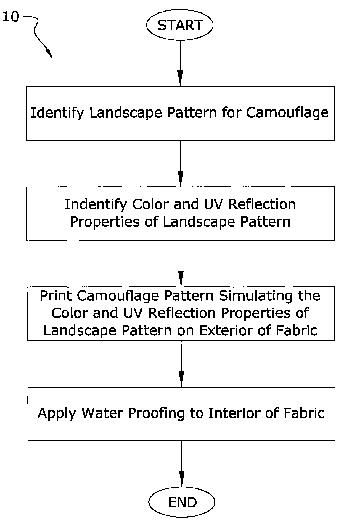
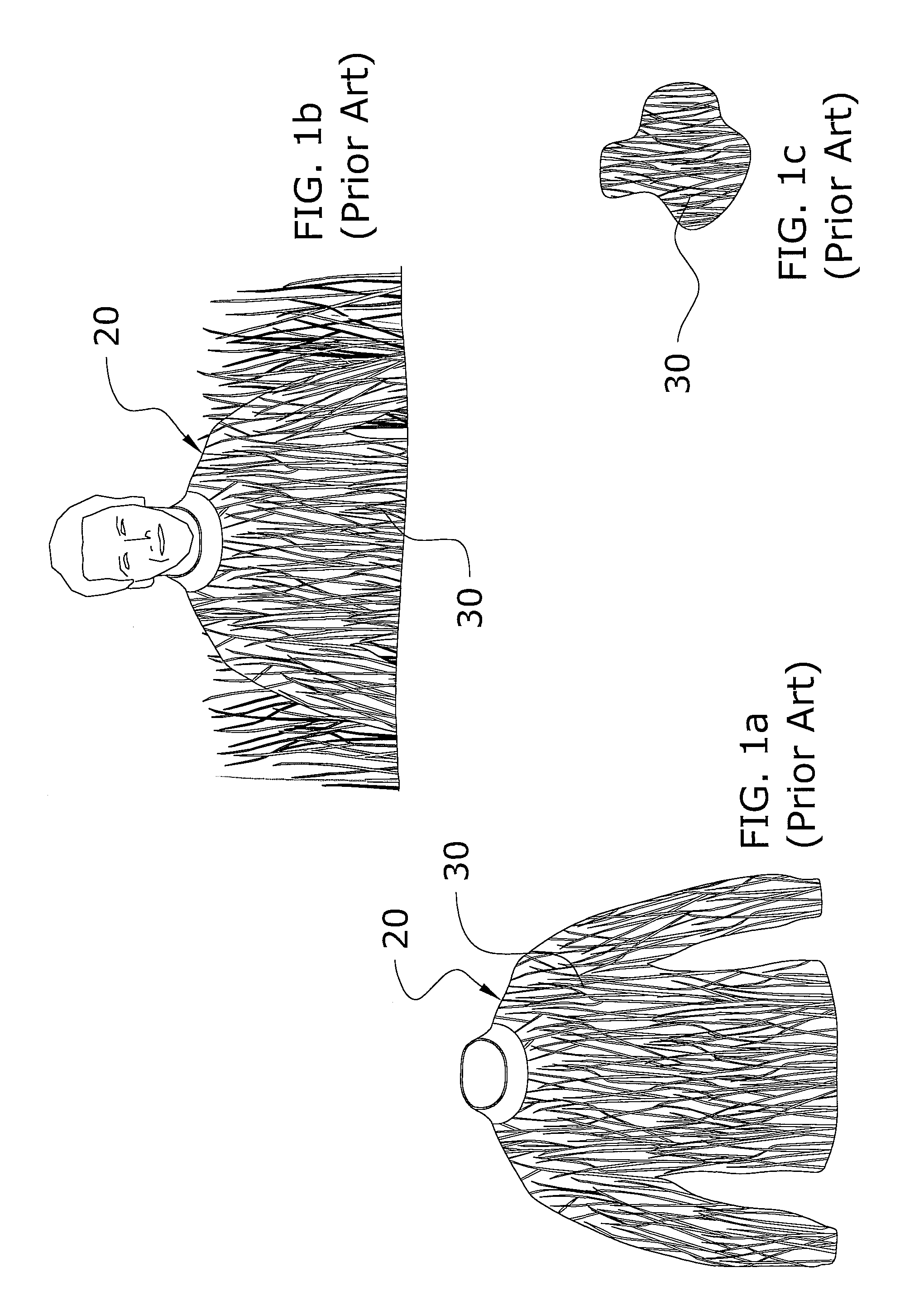
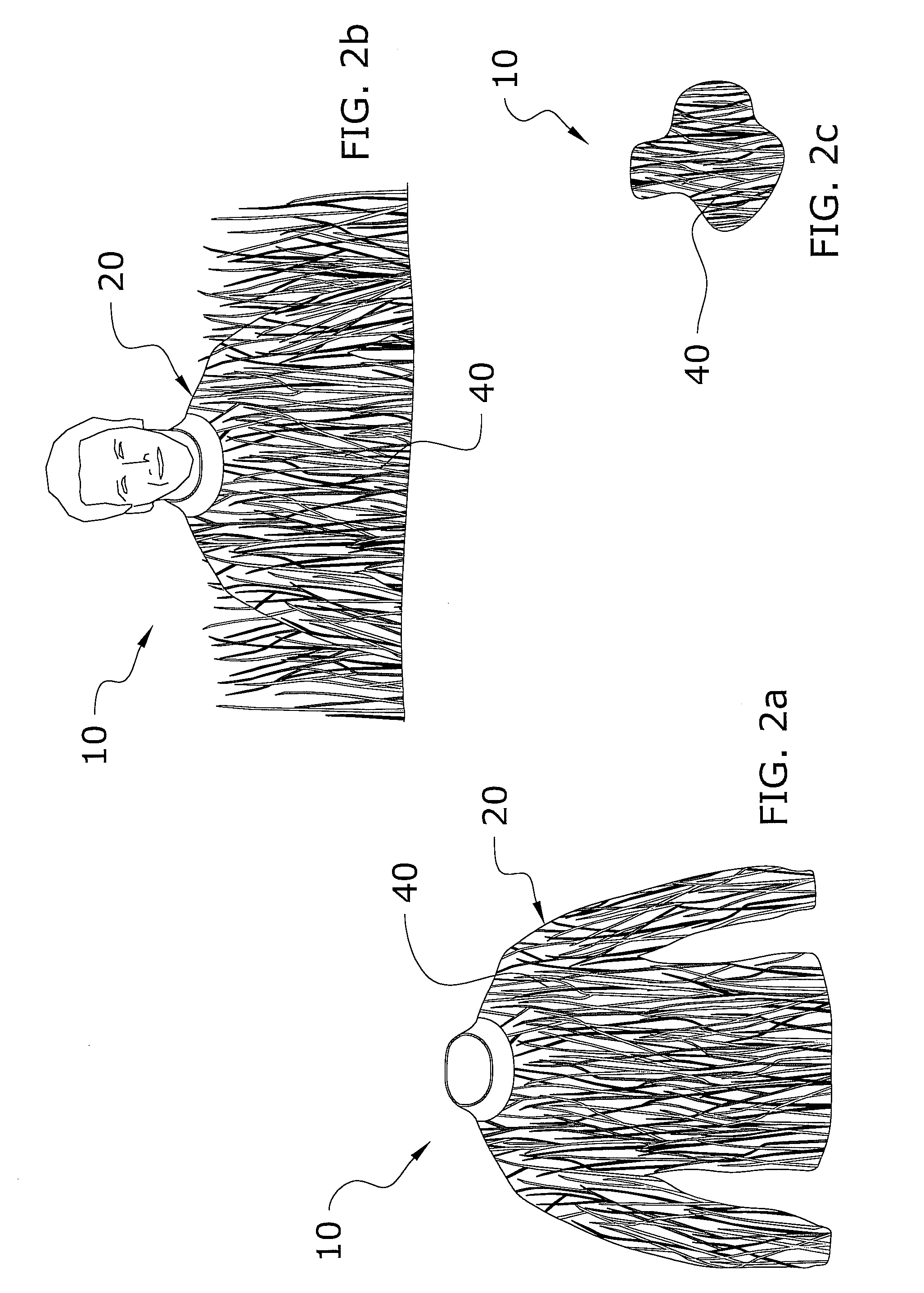
[0031]Turning now descriptively to the drawings, in which similar reference characters denote similar elements throughout the several views, FIGS. 1 through 3 illustrate a UV camouflage system 10, which comprises identifying a landscape pattern for camouflage, identifying the color and UV reflection properties of the landscape pattern, and printing a UV camouflage pattern 40 on an item that emulates the color and UV reflection properties of the landscape pattern.

B. Identifying Exterior Landscape.

[0032]The first step with the present invention is to identify an exterior landscape that is to be emulated for the camouflage pattern 40. It is desirable that the camouflage pattern 40 used on the item (e.g. clothing) have both the same visual pattern and light reflection properties as the exterior landscape to be emulated. The visual pattern is comprised of the visual shapes created by the exterior landscape (e.g. narrow blades of grass shapes, rounded leaves, thick corn stocks...


PUM

PropertyMeasurementUnit
light reflectionaaaaaaaaaa
light spectrumaaaaaaaaaa
light reflection propertiesaaaaaaaaaa

Abstract

A UV camouflage system for effectively camouflaging an individual or structure with respect to birds. The UV camouflage system generally includes identifying a landscape pattern for camouflage, identifying the color and UV reflection properties of the landscape pattern, and printing a UV camouflage pattern on an item that emulates the color and UV reflection properties of the landscape pattern.

Description

CROSS REFERENCE TO RELATED APPLICATIONS[0001]Not applicable to this application.STATEMENT REGARDING FEDERALLY SPONSORED RESEARCH OR DEVELOPMENT[0002]Not applicable to this application.BACKGROUND OF THE INVENTION[0003]1. Field of the Invention[0004]The present invention relates generally to hunting camouflage and more specifically it relates to a UV camouflage system for effectively camouflaging an individual or structure with respect to birds.[0005]2. Description of the Related Art[0006]Any discussion of the related art throughout the specification should in no way be considered as an admission that such related art is widely known or forms part of common general knowledge in the field.[0007]The visible light spectrum for humans extends only between 400 nm to 700 nm. The light spectrum above 700 nm is not visible to humans and is comprised of infrared light. The light spectrum below 400 nm is also not visible to humans and is comprised of ultraviolet light. Ultraviolet light is usua...

Claims


Application Information

Patent Timeline
Patent Type & Authority Patents(United States)
IPC IPC(8): B05D5/06
CPCF41H3/00D06P1/004F41H3/02
Inventor BUTZ, SCOTT A.
Owner REEL WINGS DECOY
Learn More