
Variable valve activation system for internal combustion engine

a technology of activation system and internal combustion engine, which is applied in the direction of valve arrangement, machines/engines, mechanical equipment, etc., can solve the problems of increasing the restrictions on the head structure, poor lubrication, and restricted activation system of variable valve, so as to reduce the space necessary to shift the parts around the swing fulcrum of the first arm, increase the mounting performance of the internal combustion engine, and vary the lift amount of the engine valv

Inactive Publication Date: 2012-10-02
SUZUKI MOTOR CORP
View PDF14 Cites 3 Cited by
  • Summary
  • Abstract
  • Description
  • Claims
  • Application Information

AI Technical Summary

Benefits of technology

The invention is a variable valve activation system for internal combustion engines that can change the lift of engine valves by adjusting the position of a swing cam. The system includes a first arm driven by a camshaft, a swing cam linked with the first arm, and a variable mechanism for adjusting the position of the swing cam. The system uses a gear mechanism to transmit the movement of the first arm to the swing cam. Compared to conventional systems, the invention reduces the space needed to shift parts and allows for a smaller drive cam and first arm, increasing mounting performance on the engine. The system also allows for changing the gear ratio between the first and second gears to adjust the lift of the engine valve, improving performance on engines with different lift requirements.

Problems solved by technology

As a result, the variable valve activation system is restricted to be mounted on the cylinder head.
As a result, the size of the link structure within a cylinder head increases, resulting in an increase of the restrictions on the head structure (for example, interference between the swing shaft and the drive cam or the like).
Due to the cam profile, there may arise a problem such that lubrication becomes poor (increase of friction and wear), or optimization of the valve lift may be restricted (for example, increase of external diameter of the tappet).

Method used


Image

  • Variable valve activation system for internal combustion engine
  • Variable valve activation system for internal combustion engine
  • Variable valve activation system for internal combustion engine

Examples


Embodiment Construction

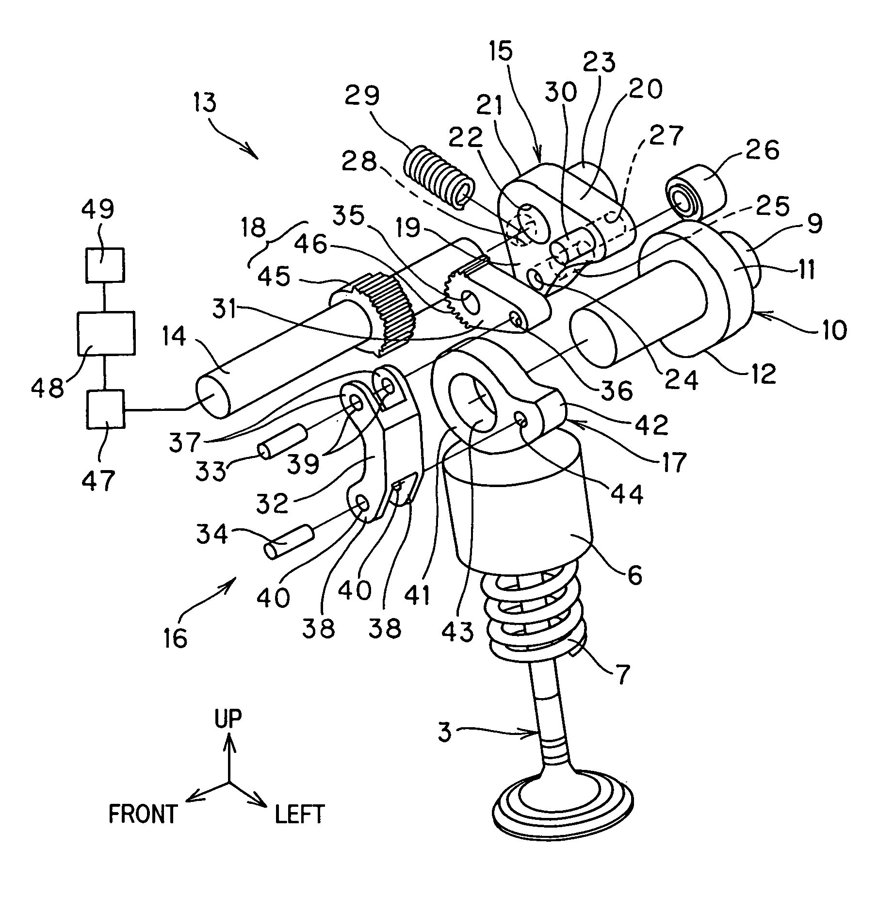
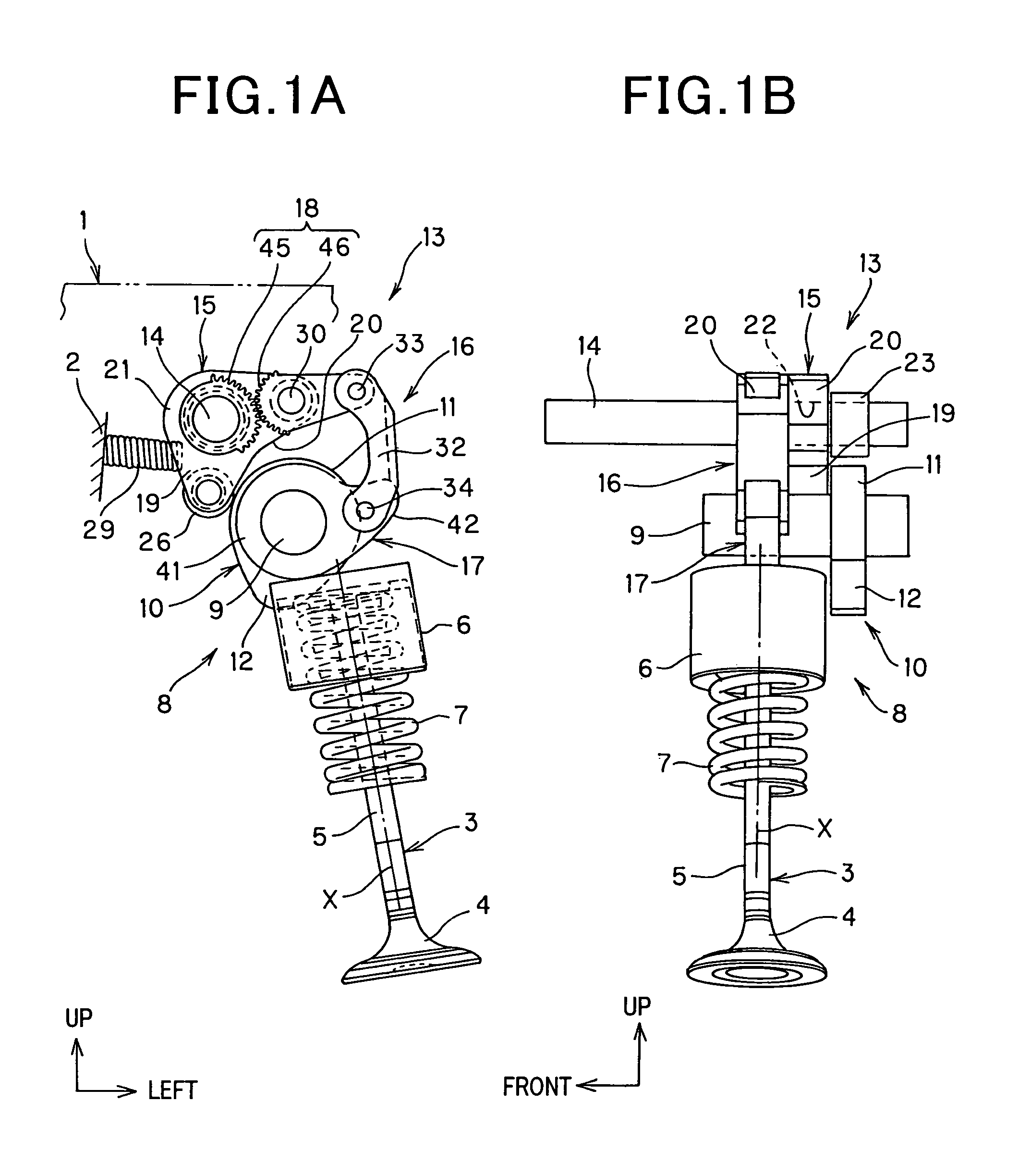
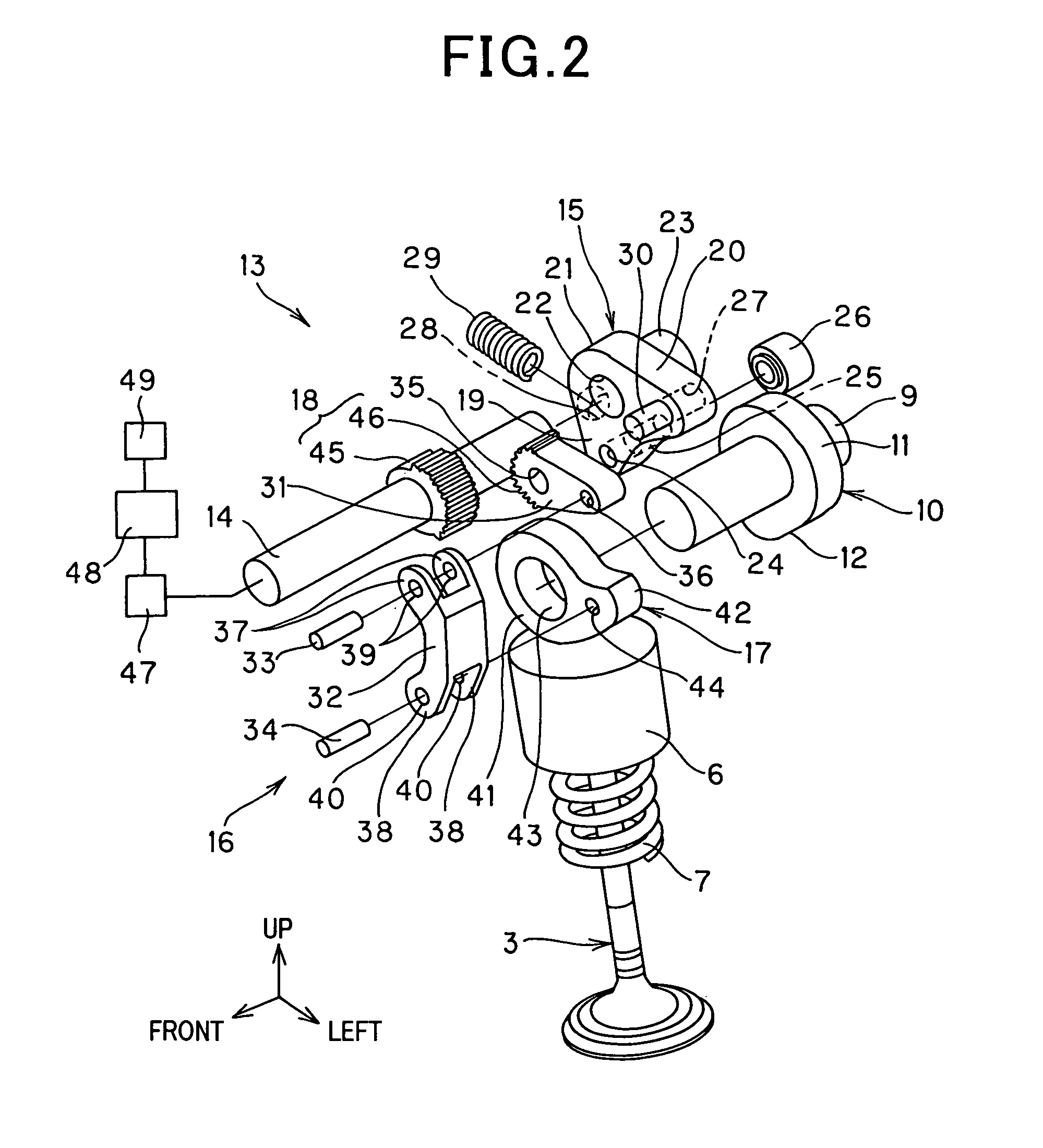
[0028]The invention is intended to achieve a variable valve activation system having a variable mechanism including a first gear concentrically provided with a swing shaft of a first arm and a second gear provided to a second arm concentrically with a link pin so as to engage with the first gear to thereby vary the lift amount of the engine valve. Thus the variable valve activation system is downsized and the mounting performance on an internal combustion engine is increased as the volume of the valve activation system with an engine compartment is advantageously minimized.

[0029]Embodiments of the invention will be described below with reference to the drawings.

[0030]FIG. 1(A) to FIG. 4(B) show an embodiment of the invention.

[0031]In FIG. 1(A), FIG. 1(B) and FIG. 2, an internal combustion engine 1 and a cylinder head 2 are illustrated. The internal combustion engine 1 is mounted vertically with a crankshaft oriented in a front-rear direction of a vehicle. The cylinder head 2 located...


PUM


Abstract

Variable valve activation system for internal combustion engines includes a first arm, a link mechanism, a swing cam, and a variable mechanism, which continuously varies lift amount of an engine valve. The link mechanism includes a second arm rotatably linked with the first arm for transmitting the movement of the first arm to the swing cam. The variable mechanism includes a first gear provided concentrically with a swing shaft of the first arm and a second gear provided to the second arm concentrically with the link pin so as to engage with the first gear. The rotation of the first gear causes the second arm to swing and varies the swing position of the swing cam with respect to the engine valve, and in a state the first gear is in a halt or stopped position, the first arm causes the second arm to swing in a swing direction of the first arm.

Description

FIELD OF THE INVENTION[0001]The present invention relates to a variable valve activation system for internal combustion engines, and particularly to a variable valve activation system for internal combustion engines capable of downsizing of the variable valve activation system and increasing mounting performance thereof by providing a compact arrangement on an internal combustion engine.BACKGROUND OF THE INVENTION[0002]In order to increase the combustion stability during low speed operation under a small load and to ensure the output during high speed operation under a large load, some internal combustion engines mounted on a vehicle or the like are provided with a variable valve activation system. The variable valve activation system changes lift timing and lift amount of an engine valve, like an intake or exhaust valve. The engine valve is driven to open / close by a drive cam provided to a camshaft of a valve train corresponding to the operation status of the internal combustion en...

Claims


Application Information

Patent Timeline
Patent Type & Authority Patents(United States)
IPC IPC(8): F01L1/34
CPCF01L13/0015F01L13/0063F01L2013/0073F01L2105/00F01L2820/032F01L2305/00
Inventor INATA, HIROKI
Owner SUZUKI MOTOR CORP
Learn More