
Beamforming with partial channel knowledge

a beamformer and partial channel technology, applied in the direction of antennas, antenna details, electrical equipment, etc., can solve the problems of partial channel knowledge, beamformees may not send the known signal to the beamformer using all available transmit antennas

Active Publication Date: 2012-09-25
NXP USA INC
View PDF8 Cites 5 Cited by
  • Summary
  • Abstract
  • Description
  • Claims
  • Application Information

AI Technical Summary

Benefits of technology

This approach enables effective data transmission by utilizing the null space to steer remaining streams, ensuring reliable communication even with partial channel knowledge, improving data throughput and reducing interference in MIMO systems.

Problems solved by technology

Although beamforming with full channel knowledge and beamforming with no channel knowledge are effective techniques, in some situations, only partial channel knowledge exists.
Sometimes, however, the beamformee may not send the known signal to the beamformer using all available transmit antennas.

Method used


Image

  • Beamforming with partial channel knowledge
  • Beamforming with partial channel knowledge
  • Beamforming with partial channel knowledge

Examples


Embodiment Construction

[0021]The present invention relates to beamforming with partial channel knowledge. The following description is presented to make and use the invention and is provided in the context of a patent application and its requirements. Various modifications to the preferred embodiments and the generic principles and features described herein will be readily apparent to those skilled in the art. Thus, the present invention is not intended to be limited to the embodiments shown, but is to be accorded the widest scope consistent with the principles and features described herein.

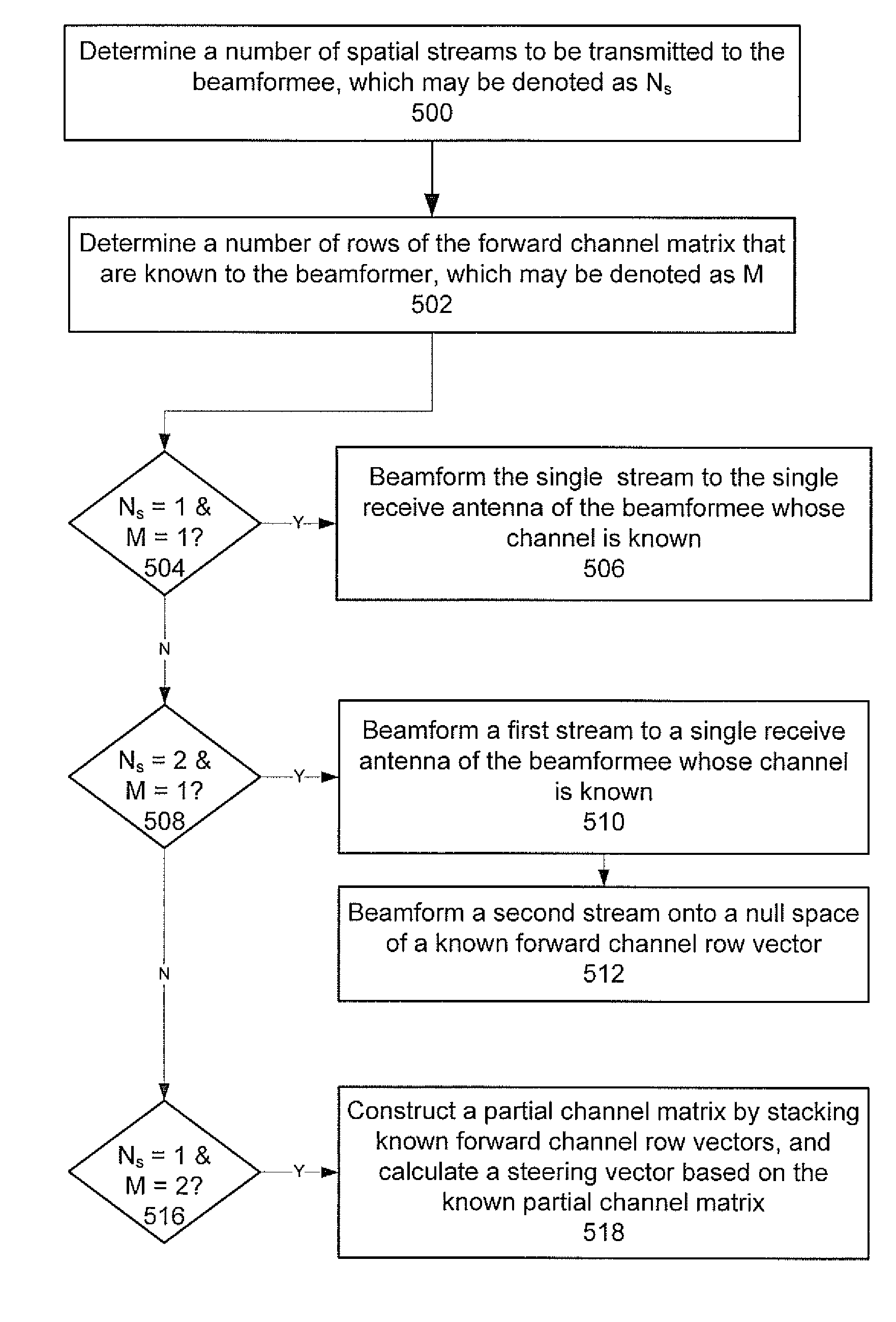
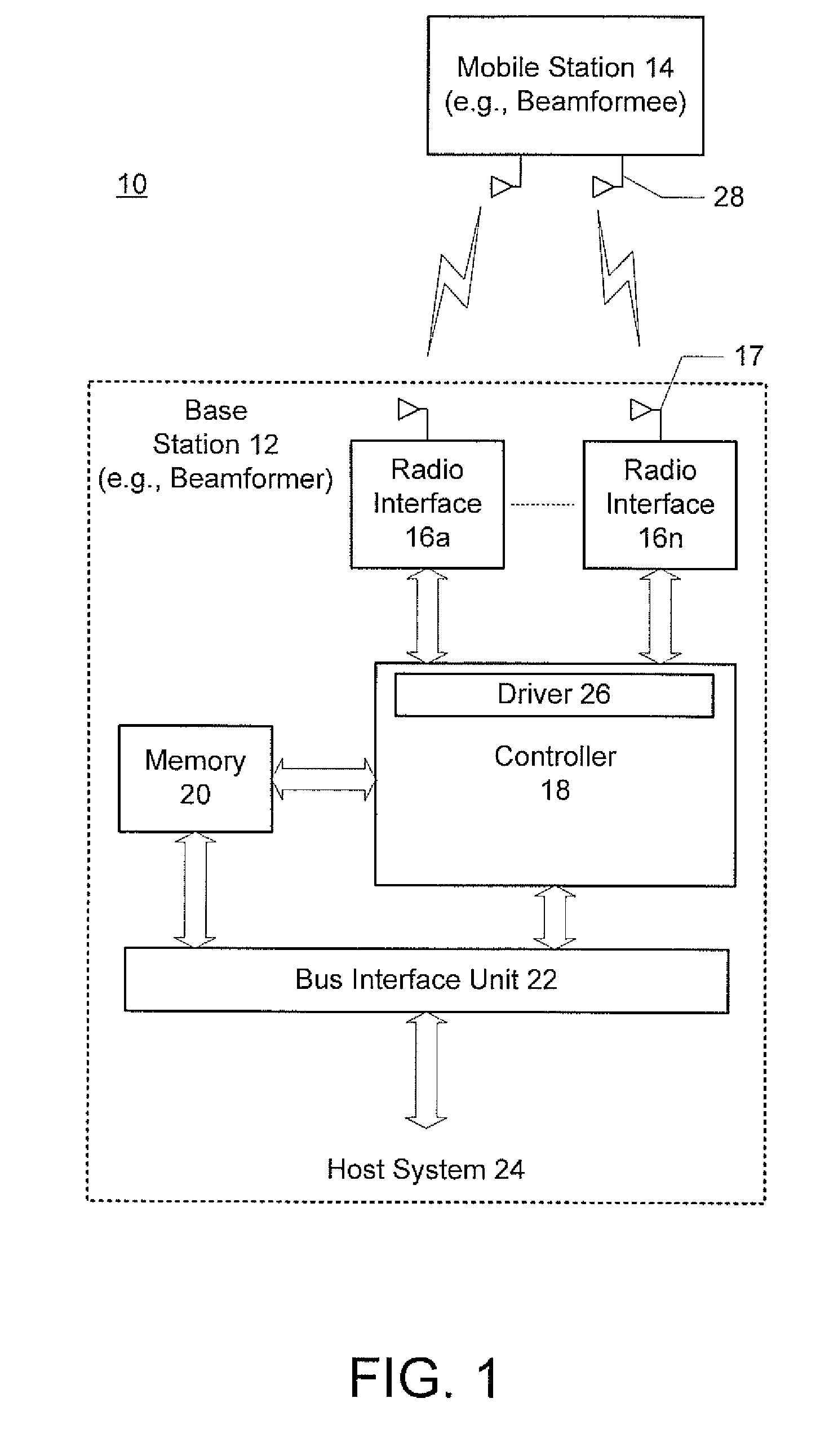
[0022]The preferred embodiment provides methods and systems for beamforming with partial channel knowledge for use in MIMO devices. The exemplary embodiments will be described in terms of MIMO beamforming in the context of an exemplary downlink cellular system comprising a base station and a mobile station. However, the exemplary embodiments are applicable to any MIMO system and other types of wireless communication de...


PUM


Abstract

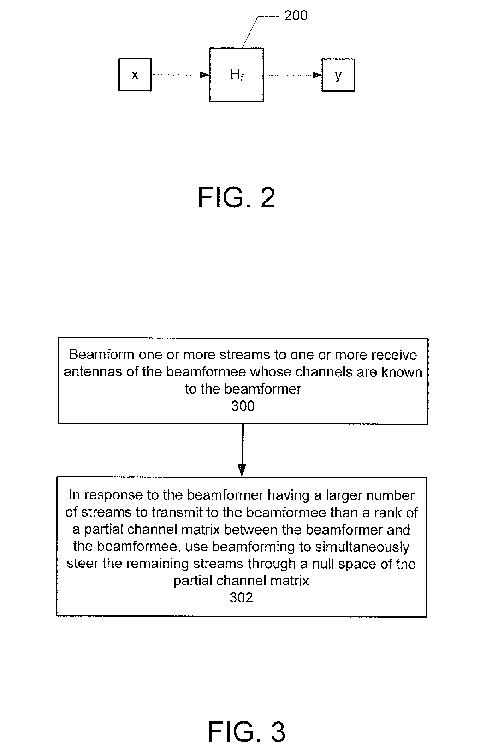
An apparatus for use in transmit beamforming to a beamformee having NR receive antennas. The apparatus includes a controller configured to i) construct a partial channel matrix that describes a multiple input, multiple output (MIMO) channel between a beamformer and M receive antennas, wherein M is less than NR, and ii) generate L independent vectors using the partial channel matrix, wherein L is a rank of the partial channel matrix. When a number NS of one or more streams is greater than L, the controller is further configured to i) select the L independent vectors as steering vectors to steer L streams of the plurality of streams, and ii) select NS−L orthogonal vectors in a null space of the L independent vectors as steering vectors to steer a remainder of the streams in the plurality of streams.

Description

CROSS-REFERENCE TO RELATED APPLICATIONS[0001]This application is a continuation of U.S. Application No. 13 / 030,738, filed on Feb. 18, 2011, which is a continuation of U.S. application Ser. No. 12 / 192,264 (now U.S. Pat. No. 7,893,871), filed on Aug. 15, 2008, which claims priority under 35 U.S.C. §119(e) to U.S. Provisional Application No. 60 / 978,942, filed on Oct. 10, 2007.BACKGROUND[0002]The basis of multiple-input / multiple-output (MIMO) operation is to provide wireless devices with multiple radio interfaces to allow the devices to send data on different channels at the same time in order to achieve greater transmit / receive data rates and with greater reliability. In MIMO systems, a transmitter sends multiple streams of encoded data packets to a receiver by multiple transmit antennas. The streams may be spatially and time encoded and converted into multiple RF signals. The signals are transmitted to the receiver on multiple channels between multiple transmit antennas at the transmi...

Claims


Application Information

Patent Timeline
Patent Type & Authority Patents(United States)
IPC IPC(8): H01Q3/00
CPCH01Q1/246H01Q25/00H01Q21/293H01Q21/06
Inventor LEE, JUNGWONNABAR, ROHIT U.
Owner NXP USA INC
Learn More