
Display apparatus

a display device and display screen technology, applied in the direction of electrical apparatus, electrical apparatus contruction details, cooling/ventilation/heating modifications, etc., can solve the problems of deteriorating the visibility of the display screen, misting of the surface, and temperature difference between the outside air and the air inside,

Active Publication Date: 2012-09-18
SANYO ELECTRIC CO LTD
View PDF7 Cites 54 Cited by
  • Summary
  • Abstract
  • Description
  • Claims
  • Application Information

AI Technical Summary

Problems solved by technology

However, since the air inside the chamber does not contact outside air, a temperature difference occurs between the outside air and the air inside the chamber when the outside air temperature falls.
When the temperature of the outside air becomes lower than the temperature inside the chamber, moisture included in the air inside the chamber is condensed to dew drop on an inner surface of a glass portion provided in front of the panel, and as a result, the inner surface is misted and it may deteriorate the visibility of a screen of the panel.
Further, when the panel is accommodated in the chamber, the temperature in the chamber tends to increase due to the heat generated from the panel.
Therefore, the temperature of the panel could rise to deteriorate the function of the panel, and it may result in inability of the panel to display images.
However, since the dew condensed water is left untreated, the condensed water evaporates and is contained in the air inside the chamber again, when the cooling device stops its operation.
Accordingly, the inner surface of the glass portion cannot be prevented from being misted.

Method used


Image

  • Display apparatus
  • Display apparatus
  • Display apparatus

Examples


Embodiment Construction

[0017]A display apparatus according to an embodiment of the present invention is discussed in detail below with reference to drawings.

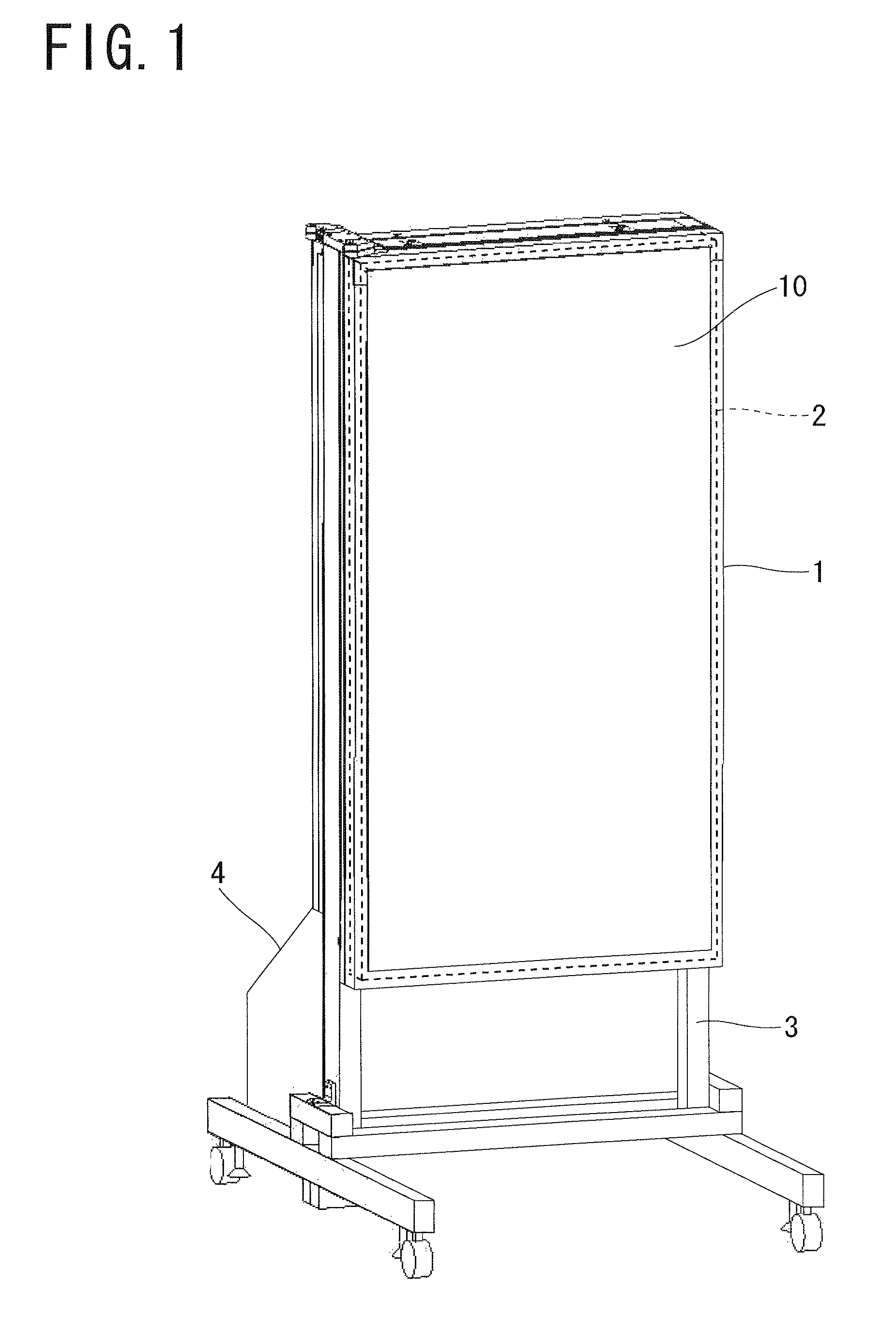
[0018]As shown in FIG. 1, the display apparatus comprises a housing 1, a liquid crystal display panel 2 arranged in the housing 1, a support base 3 for supporting the housing 1, and a cooling device 4. The support base 3 has a caster attached thereto. The panel 2 utilizes a light emitting diode (LED) as a light source for image display.

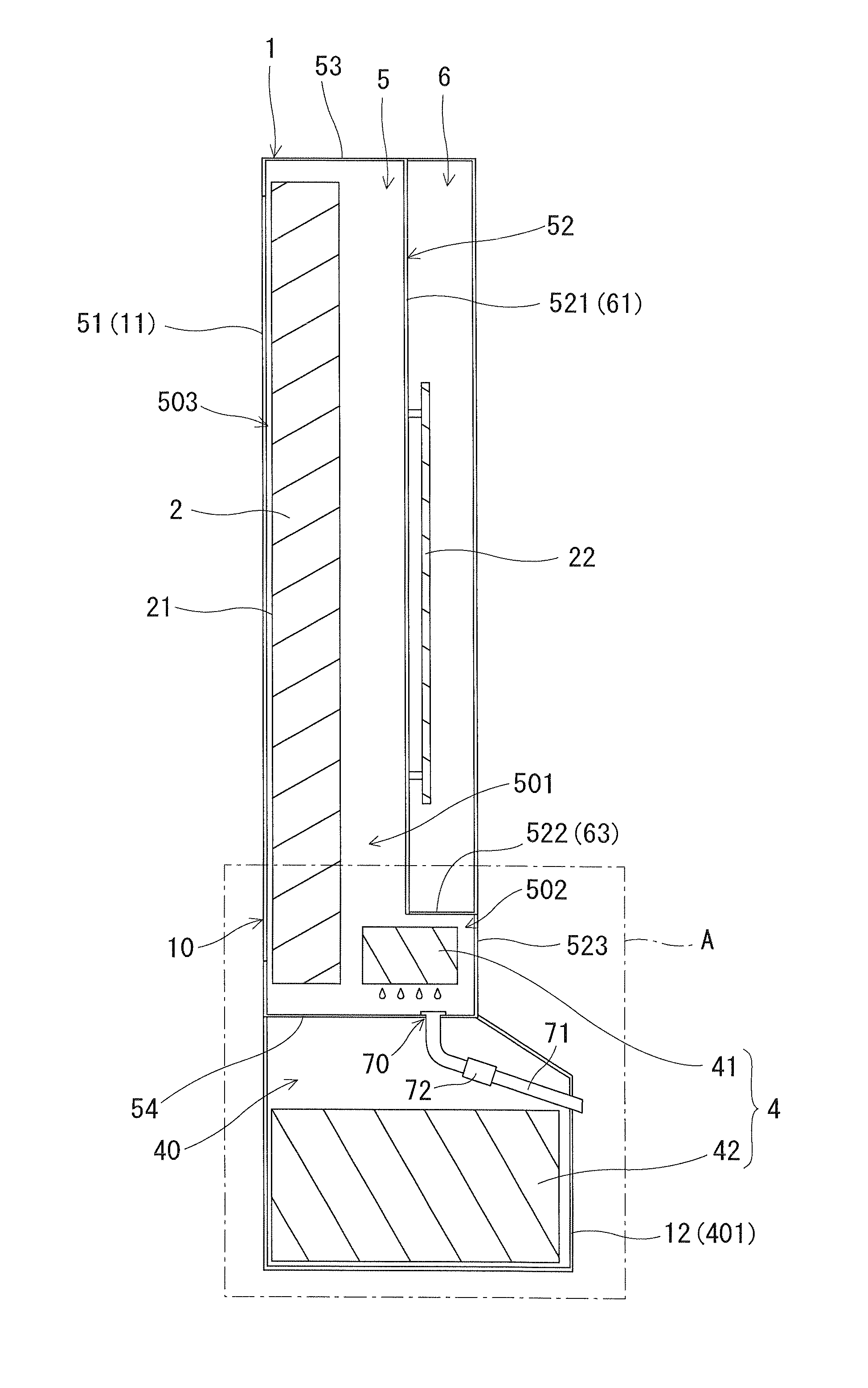
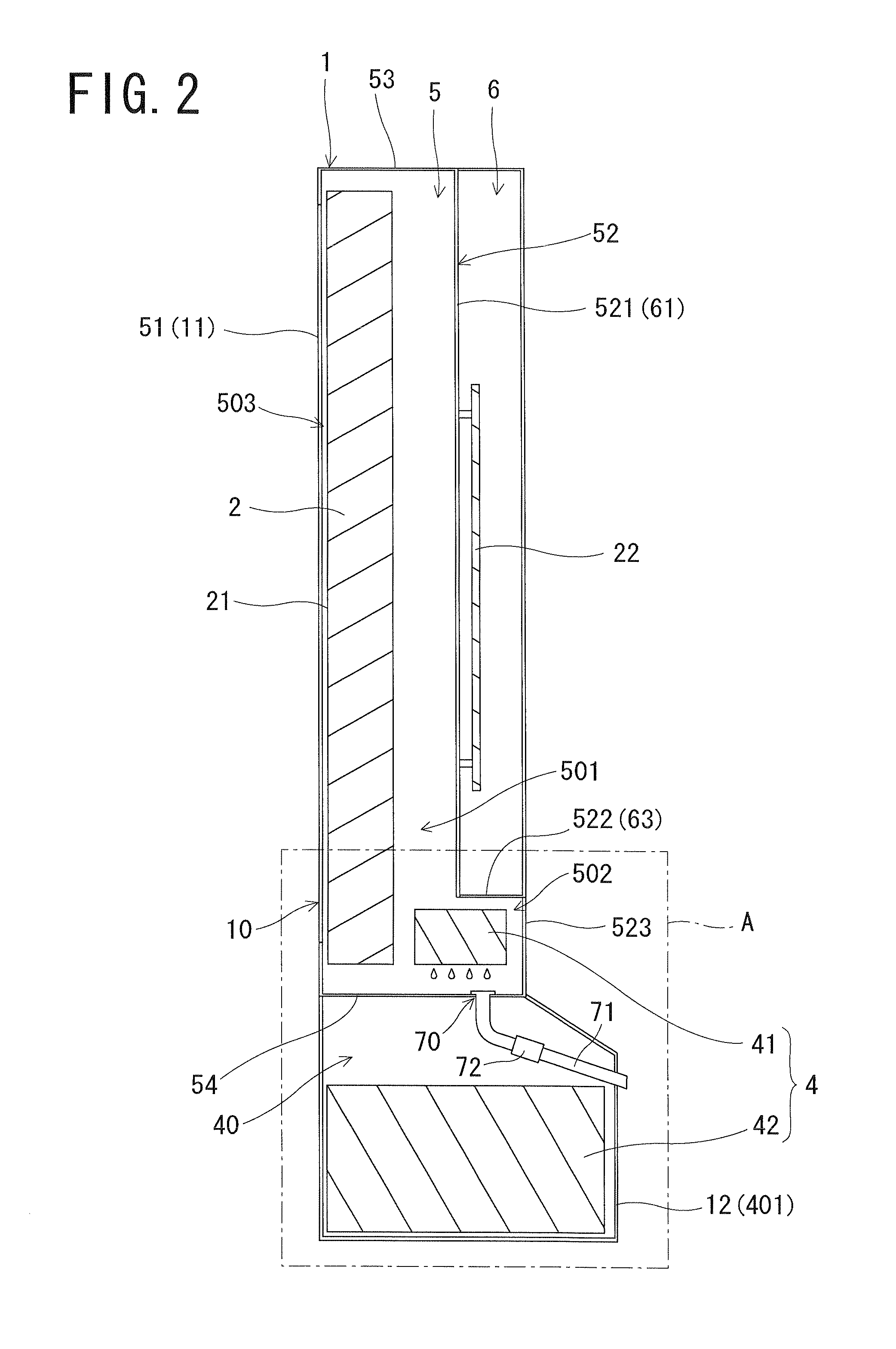
[0019]As shown in FIG. 2, the housing 1 includes therein a first accommodation chamber 5 having a sealed structure and a second accommodation chamber 6 having a waterproofing structure. A front wall 51 of the chamber 5 is formed by a front wall 11 of the housing 1, and the wall 11 is made of an optically transparent material such as a glass material. In contrast, an upper wall 53, a bottom wall (lower wall), both side walls (i.e. left side wall and right side wall) and a rear wall 52 of the chamber 5 are made of a metal...


PUM


Abstract

A display apparatus includes an accommodation chamber having a sealed structure, a display panel accommodated in the accommodation chamber, a cooling part which cools the air inside the accommodation chamber, a drain pipe extending from a bottom part of the accommodation chamber, and a check valve provided in the drain pipe.

Description

[0001]The Japanese patent applications Number 2009-200866 and 2009-200867, upon which this patent application is based, are hereby incorporated by reference.BACKGROUND OF THE INVENTION[0002]1. Field of the Invention[0003]The present invention relates to a display apparatus with a cooling device.[0004]2. Description of Related Art[0005]In recent years, flat panel display apparatuses for outdoor installation have appeared. In such an apparatus, in order to protect the panel from weather, dust and the like, it is considered to arrange the panel inside an accommodation chamber having a sealed structure.[0006]However, since the air inside the chamber does not contact outside air, a temperature difference occurs between the outside air and the air inside the chamber when the outside air temperature falls. When the temperature of the outside air becomes lower than the temperature inside the chamber, moisture included in the air inside the chamber is condensed to dew drop on an inner surfac...

Claims


Application Information

Patent Timeline
Patent Type & Authority Patents(United States)
IPC IPC(8): H05K7/20
CPCH05K7/20972
Inventor NAKAMICHI, MASAYATAKAHASHI, SHOHEI
Owner SANYO ELECTRIC CO LTD
Learn More