
Image processing device and image processing method

a technology of image processing and image sensor, applied in the direction of instruments, television systems, signal generators with optical-mechanical scanning, etc., can solve the problems of increasing the amount of data read from the imaging sensor per unit time, and it is difficult to read data of all pixels at a high frame rate, so as to suppress the deterioration of image quality

Active Publication Date: 2012-09-11
PANASONIC INTELLECTUAL PROPERTY CORP OF AMERICA
View PDF17 Cites 9 Cited by
  • Summary
  • Abstract
  • Description
  • Claims
  • Application Information

AI Technical Summary

Benefits of technology

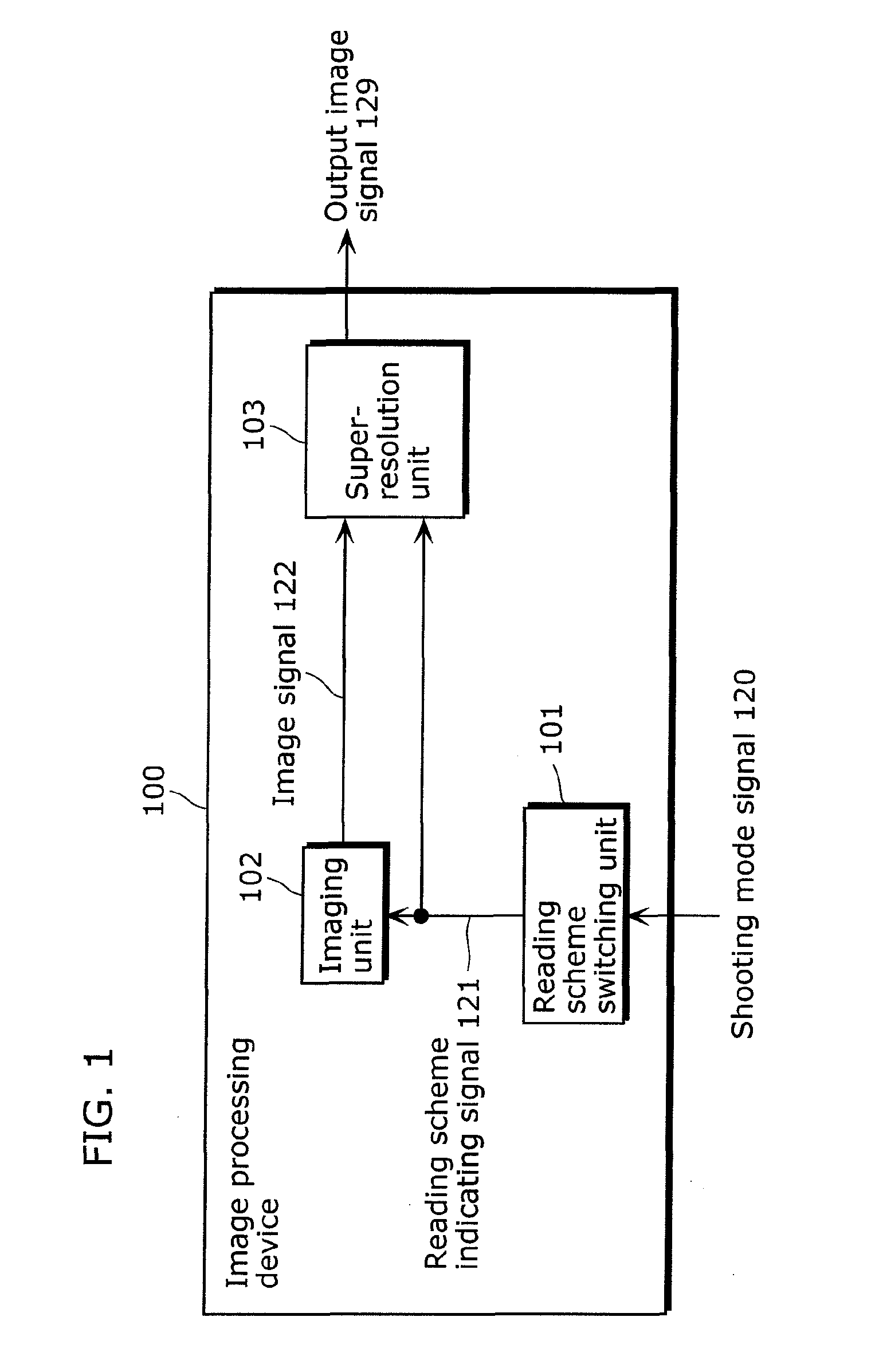
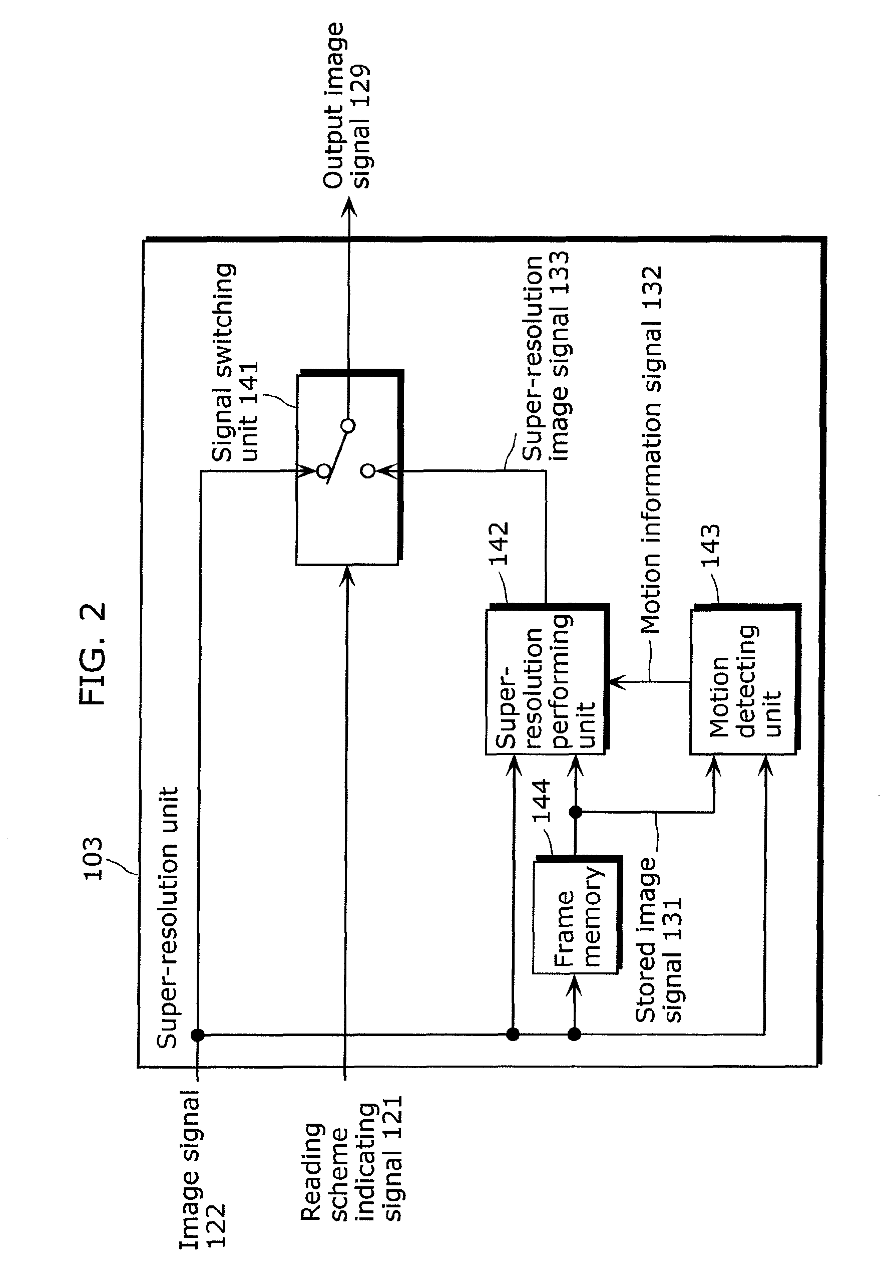
The present invention relates to an image processing device and method that can perform a resolution up-converting process on low-resolution image data captured by an imaging sensor. The device includes a reading scheme switching unit that receives a shooting mode signal and outputs a reading scheme indicating signal to the imaging unit. The imaging unit reads the image data and outputs an image signal. The device also includes a super-resolution unit that receives the image signal and a stored image signal and performs a super-resolution process on the thinned-pixels read and low-resolution image signal to output a high-resolution image signal. The device can switch between a high-speed reading mode and a regular reading mode based on the reading scheme indicating signal. The technical effect of the invention is to enable high-speed continuous shooting or moving picture shooting modes while reducing the amount of data read per unit time.

Problems solved by technology

However, shooting an image at a high frame rate by using the imaging sensor such as continuous shooting and moving picture shooting increases an amount of data read from the imaging sensor per unit time.
Accordingly, an imaging sensor in which an amount of data read per unit time is limited makes it difficult to perform image shooting at a high frame rate while reading data of all the pixels.

Method used


Image

  • Image processing device and image processing method
  • Image processing device and image processing method
  • Image processing device and image processing method

Examples


embodiment 1

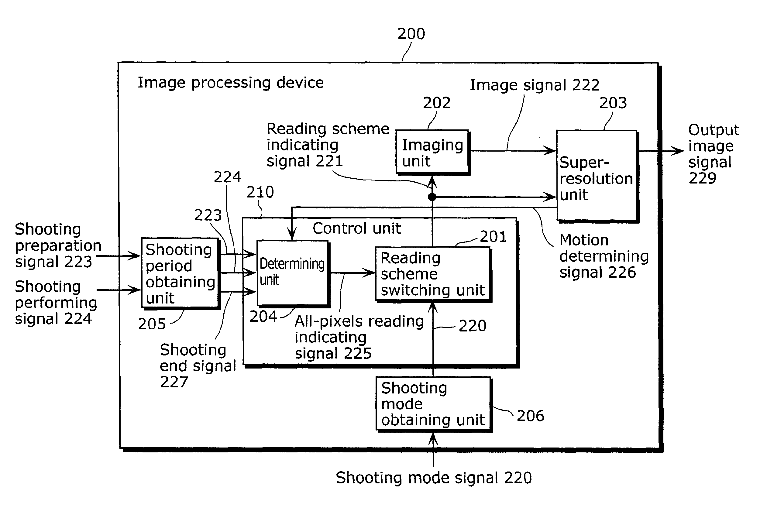
[0130]In a high-speed reading mode, an image processing device 200 according to Embodiment 1 of the present invention shoots a high-resolution image during a period other than a shooting period, and performs a super-resolution process on a low-resolution image shot during the shooting period, using the high-resolution image. As a result, the image processing device 200 according to Embodiment 1 of the present invention suppresses a deterioration in image quality in the high-speed reading mode.

[0131]First, a structure of the image processing device 200 according to Embodiment 1 of the present invention will be described with reference to FIG. 8. FIG. 8 is a diagram showing the structure of the image processing device 200 according to Embodiment 1 of the present invention.

[0132]The image processing device 200 shown in FIG. 8 is, for example, a system LSI mounted on a digital still camera. The image processing device 200 receives a shooting mode signal 220, a shooting preparation signa...

embodiment 2

[0199]In addition to the functions of the above-described image processing device 200 according to Embodiment 1 of the present invention, an image processing device 300 according to Embodiment 2 of the present invention further switches an imaging method between thinned-pixels reading and all-pixels reading depending on whether or not a monitor display is performed. In addition, the image processing device 300 according to Embodiment 2 of the present invention performs a super-resolution process using the temporally closest high-resolution frame.

[0200]FIG. 17 is a block diagram showing a structure of the image processing device 300 according to Embodiment 2 of the present invention. It is to be noted that the same numerals are given to the same components as FIG. 8, and descriptions overlapping with Embodiment 1 are not described.

[0201]In addition to the structure of the image processing device 200 shown in FIG. 8, the image processing device 300 further includes a monitor display u...

embodiment 3

[0231]Embodiment 3 of the present invention will describe an example of causing an independent computer system to execute the processes described in each of the above-mentioned embodiments by recording, on a recording medium such as a flexible disk, a program for realizing the structure of the image processing device 200 or 300 described in a corresponding one of the embodiments.

[0232]FIGS. 21A to 21C each are a schematic diagram showing a case where a computer system implements the image processing device described in each embodiment, using a program recorded on a recording medium such as a flexible disk.

[0233]FIG. 21A is a diagram showing an example of a physical format of the flexible disk that is the recording medium. FIG. 21B is a diagram showing an external view of a flexible disk 450 viewed from the front, a cross section structure of the flexible disk 450, and a disk 451.

[0234]The flexible disk 450 includes a case 452 and the disk 451 included in the case 452. Tracks 453 are...


PUM


Abstract

An image processing device (200) according to the present invention includes: a shooting period obtaining unit (205) configured to obtain a shooting period; an imaging unit (202) which includes a plurality of pixels each converting light into an electrical signal, and which has a first mode in which a low-resolution image signal is outputted and a second mode in which a high-resolution image signal is outputted, the low-resolution image signal including electrical signals converted by a first number of pixels among the plurality of pixels, the high-resolution image signal including electrical signals converted by a second number of pixels among the plurality of pixels, and the second number being greater than the first number; a control unit (210) configured to cause the imaging unit (202) to operate in the first mode during the shooting period, and to operate in the second mode during a period other than the shooting period; and a super-resolution unit (203) configured to generate a super-resolution image signal by performing a resolution up-converting process on the low-resolution image signal outputted by the imaging unit (202) during the shooting period, using the high-resolution image signal outputted by the imaging unit (202) during the period other than the shooting period.

Description

TECHNICAL FIELD[0001]The present invention relates to image processing devices and image processing methods, and particularly to an image processing device which performs a resolution up-converting process on low-resolution image data imaged by using an imaging device.BACKGROUND ART[0002]In recent years, image shooting apparatuses such as digital still cameras and digital video cameras increasingly include an imaging sensor having multiple pixels in order to shoot a high-definition still image. However, shooting an image at a high frame rate by using the imaging sensor such as continuous shooting and moving picture shooting increases an amount of data read from the imaging sensor per unit time. More specifically, the amount of data read from the imaging sensor per unit time is determined by a multiplication between the number of pixels in a frame and a frame rate. Accordingly, an imaging sensor in which an amount of data read per unit time is limited makes it difficult to perform im...

Claims


Application Information

Patent Timeline
Patent Type & Authority Patents(United States)
IPC IPC(8): H04N5/228H04N7/01H04N5/76H04N5/335H04N23/40H04N25/00
CPCG06T3/4053H04N5/232H04N5/23232H04N5/343H04N2101/00H04N23/951H04N25/42
Inventor SAKAGUCHI, SATOSHITOMA, TADAMASA
Owner PANASONIC INTELLECTUAL PROPERTY CORP OF AMERICA
Learn More