
Electrical network representation of a distributed system

a distributed system and electrical network technology, applied in the direction of instruments, diagnostic recording/measuring, material impedance, etc., can solve the problems of low signal-to-noise ratio, time-consuming technique, and non-uniform reaction zones or concentrations of recirculating flows

Active Publication Date: 2012-09-11
BAKER HUGHES INC
View PDF9 Cites 9 Cited by
  • Summary
  • Abstract
  • Description
  • Claims
  • Application Information

AI Technical Summary

Problems solved by technology

Knowing the spatial distribution of the materials is particularly useful because non-uniform distribution of the materials tends to reduce the interfacial area between materials available for chemical reaction or conversion and may result in recirculating flows creating spatially non-uniform reaction zones or concentrations.
One challenge associated with these techniques is low signal-to-noise ratio.
However, this technique is more time consuming because the number of current or voltage patterns applied to the electrodes is high (typically equal to one less than the number of electrodes).

Method used


Image

  • Electrical network representation of a distributed system
  • Electrical network representation of a distributed system
  • Electrical network representation of a distributed system

Examples


Embodiment Construction

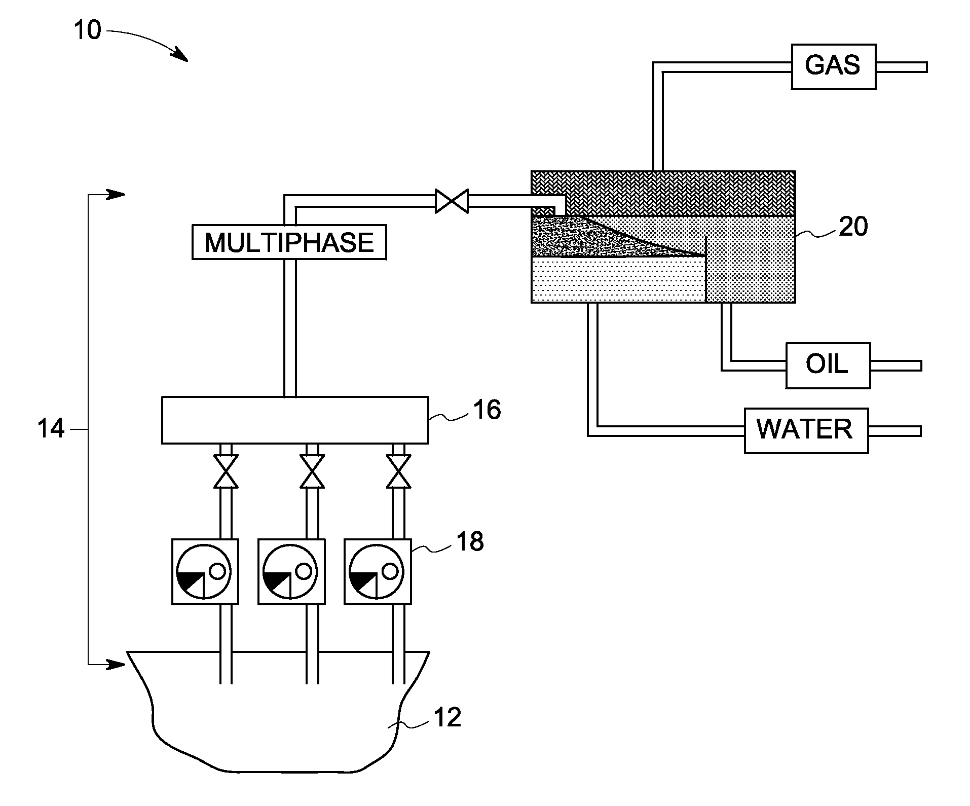
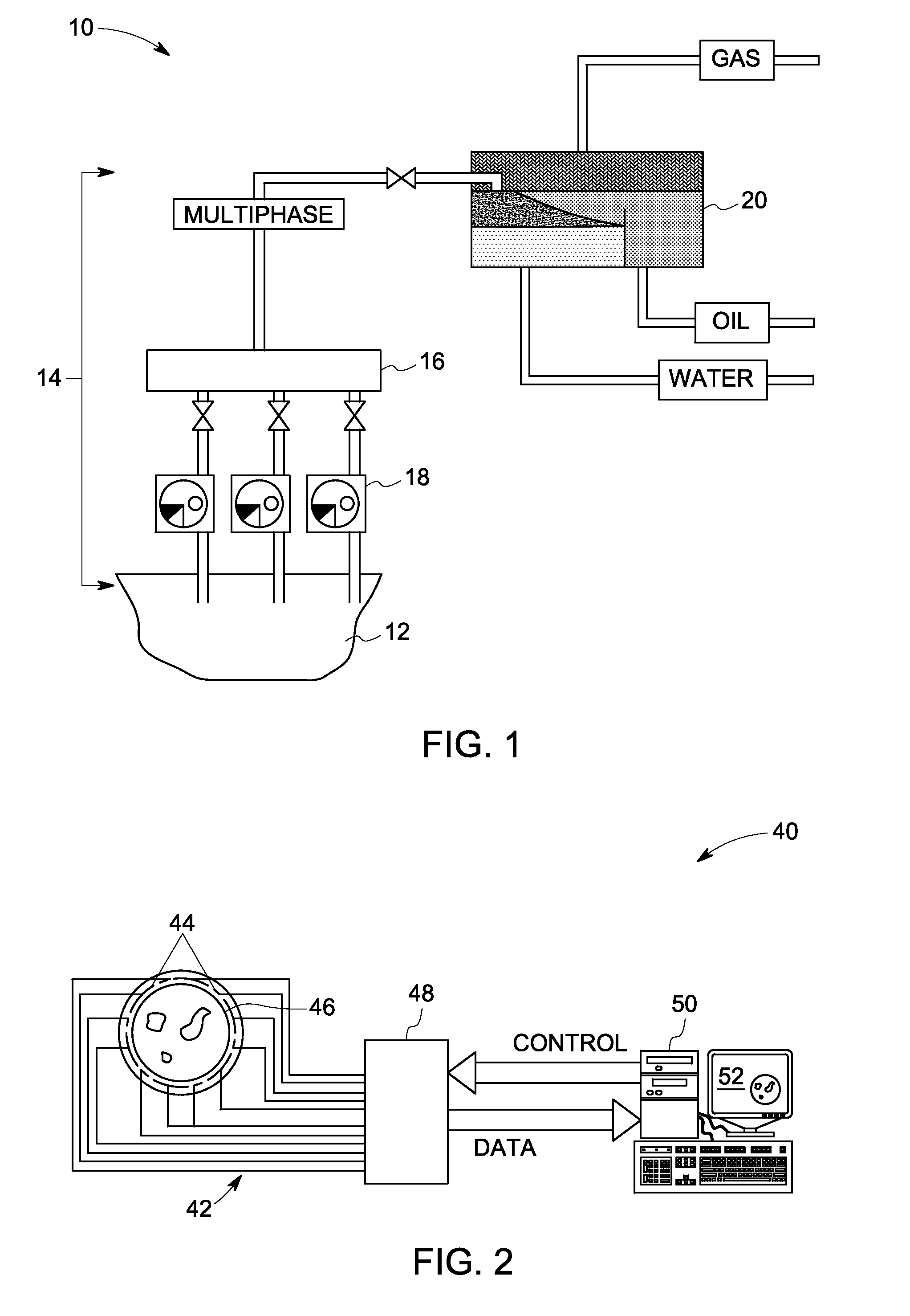
[0019]As discussed in detail below, embodiments of the present invention function to provide a system and a method for measuring characteristics of a multi-material object. In an example of a multiphase flow, the characteristics of the object may include volumetric fractions and flow rates of oil, water, and gas (in this context referencing gaseous hydrocarbons) flowing through conduits. Although the invention is described with reference to a use in oil / gas / water measurements, it is by no means limited to such applications; rather, aspects of the invention find application in a wide variety of industrial, healthcare and chemical processes such as, for example, cancer diagnosis and water treatment processes. The characteristics of such multi-material objects may be quite different from the examples given for multiphase flow.

[0020]FIG. 1 shows an oil production facility 10 according to an example embodiment. The oil production facility typically includes multiple oil wells 12 that are...


PUM


Abstract

A method for determining characteristics of a multi-material object is provided. The method includes producing a rotating electric field by providing an applied electrical signal set of individual electrical signal patterns to electrodes surrounding the multi-material object. The method also includes obtaining a measured electrical signal of electrical signals from the electrodes corresponding to each electrical signal pattern applied. An electrical network is determined based on the applied electrical signal set, the measured electrical signal set and an inverse of the applied electrical signal set. The method further includes determining the characteristics of the multi-material object by analyzing the electrical network.

Description

BACKGROUND[0001]This invention relates generally to a method for determining the composition and characteristics of the individual materials in a multi-material object, and, specifically, to a representation and analysis of the multi-material object as an electrical network.[0002]Electrical impedance tomography (EIT) is a minimally invasive measurement technique that can be used to quantitatively map material distributions within multi-material objects. In EIT, a map of the electrical conductivity and permittivity is used to infer the distributions of different materials within that object. Different current patterns or voltage patterns are applied to the object through electrodes surrounding the object, and the corresponding voltages or currents are measured. Based on the current-voltage relations, the internal impedance or internal admittance distribution is determined.[0003]One example of a multi-material object is multiphase flow in which at least two materials or phases are flo...

Claims


Application Information

Patent Timeline
Patent Type & Authority Patents(United States)
IPC IPC(8): G01R27/08
CPCG01N33/2823G01N27/02A61B5/0536
Inventor MAHALINGAM, SAKETHRAMANKOYITHITTA MEETHAL, MANOJ KUMARBANERJEE, ARIJITBASU, WRICHIKPILLAI, HARISH KUMAR
Owner BAKER HUGHES INC
Learn More