Motor for optical systems

a technology of optical systems and motors, applied in the direction of magnets, magnets, instruments, etc., can solve the problems of inability to adjust the focal length of the lens, rigid system, limited optical quality, etc., and achieve the effect of precise positioning, rapid and precise positioning of the optical system, and small power loss

Active Publication Date: 2012-09-11
KARL STORZ GMBH & CO KG
View PDF17 Cites 15 Cited by
  • Summary
  • Abstract
  • Description
  • Claims
  • Application Information

AI Technical Summary

Benefits of technology

[0012]It is further desirable to provide a motor which makes possible a rapid, continuous, and exact positioning of an optical system within as large as possible a range. With this, a path of rays through the optical system should not be blocked during a displacement of the components.
[0013]It is further desirable to provide a motor having a small power loss, so that little heat is evolved in a tip of an endoscope.
[0014]It is further desirable to provide a motor having a drive assembled from as few as possible, geometrically simple, single constructional components, so as to enables easy fabrication and assembly,

Problems solved by technology

Owing to the rod lenses, the system the system is rigid and of limited optical quality.
An adjustment of the focal length of the lens is not possible.
However, owing to the large mass of the permanent magnet, the drive is slow.
The complex construction of the drive can be well implemented with video cameras having lens diameters in a range of centimeters, but cannot be scaled to a size in a range of millimeters, which would be needed for endoscopic applications.
This results in a strong nonlinearity of the force and the displacement.

Method used


Image

  • Motor for optical systems
  • Motor for optical systems
  • Motor for optical systems

Examples


Embodiment Construction

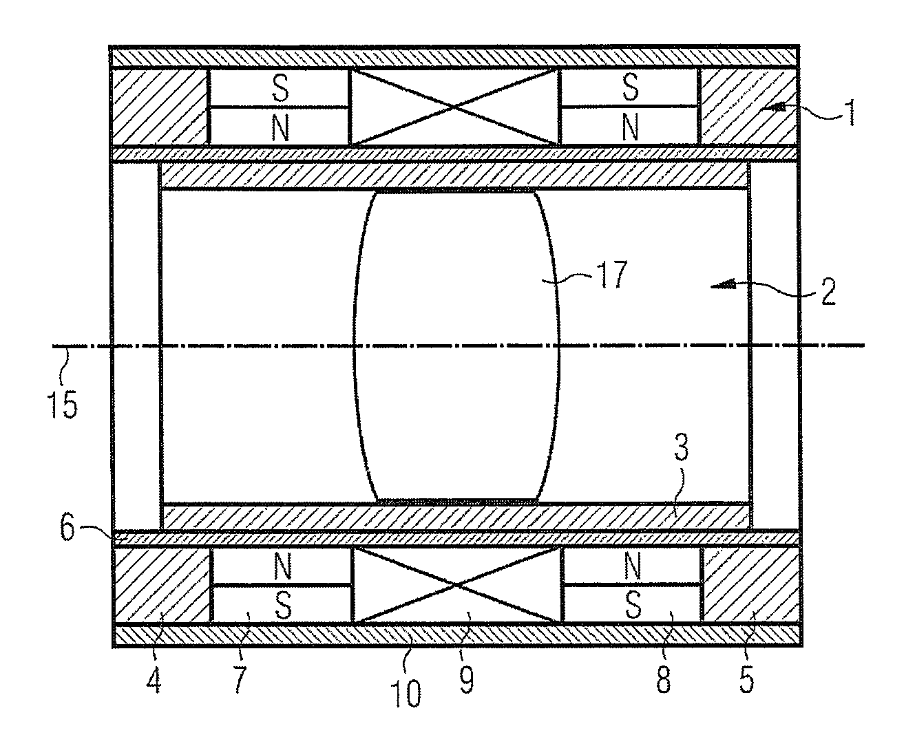
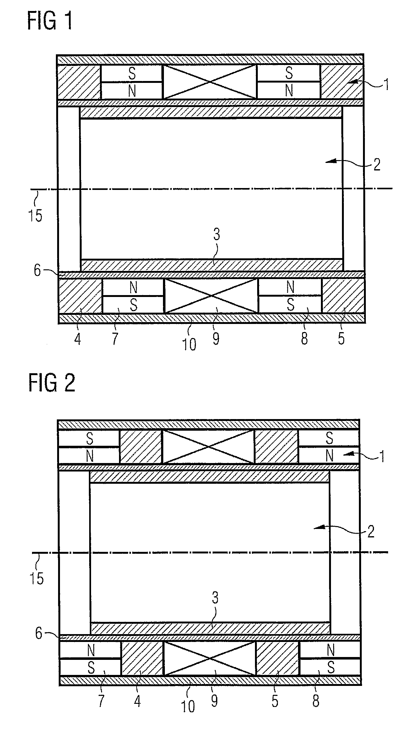
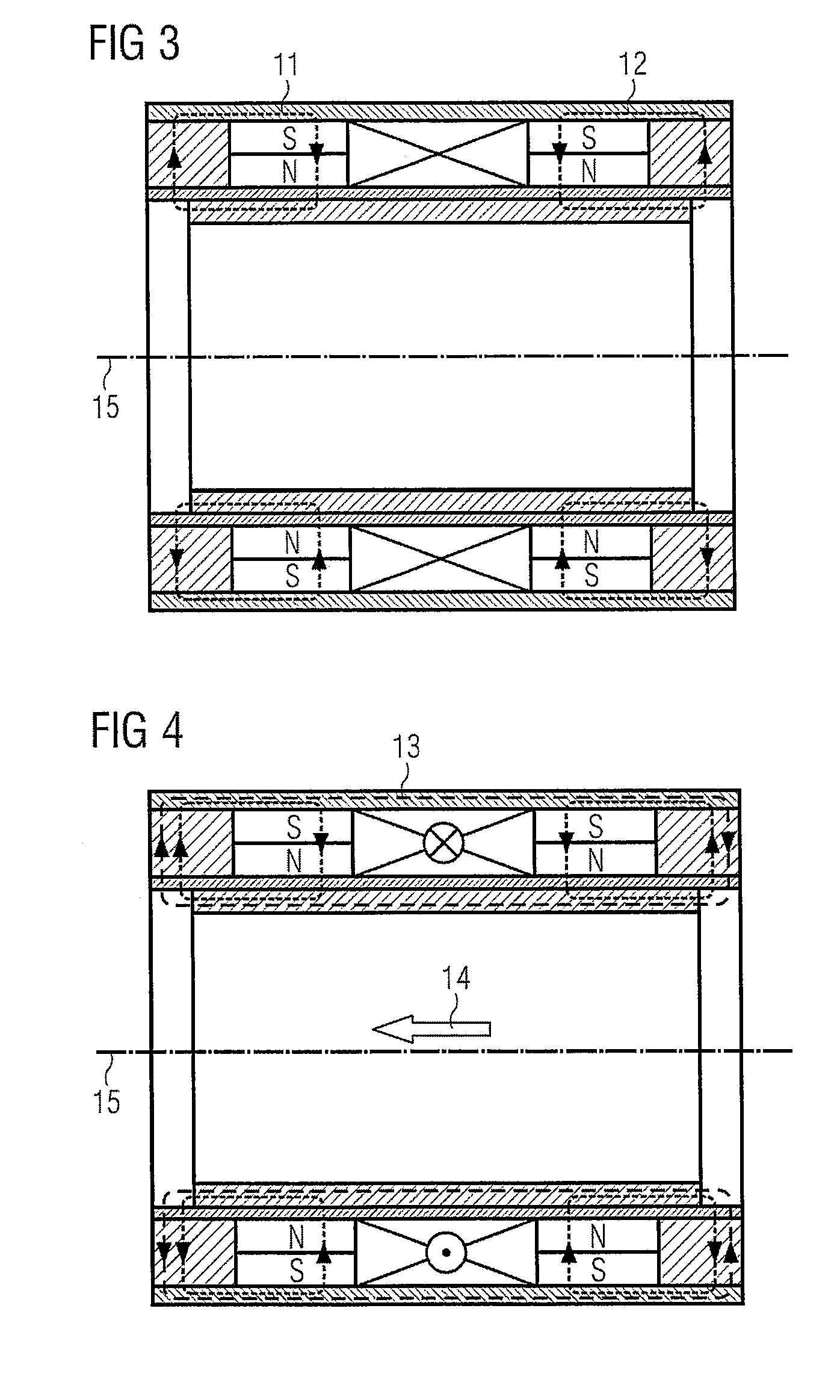
[0035]The motor for optical systems includes a stator, and also a slider that is linearly displaceable with respect thereto. In an embodiment, the motor is a linear motor. The stator has a first permanent magnet 7 and also a second, equally polarized permanent magnet 8, which magnets are magnetically interconnected by a magnetic flux return element 10. A coil 9 is disposed between the two permanent magnets. The flux return element 10 is disposed to be at least substantially parallel to a direction of movement. Furthermore, the motor has a slider with a yoke 3 which is at the same time in magnetic engagement with the first permanent magnet 7 and the second permanent magnet 8, i.e. conducts the magnetic fields of the two permanent magnets. Preferably the yoke 3 is disposed on the side of the stator facing away from the flux return element 10, and at least substantially parallel to the movement direction.

[0036]Preferably the motor is of rotational symmetry, for example of hollow-cylind...


PUM


Abstract

A motor for optical systems, for example endoscopes, has a stator with two permanent magnets having poles which are disposed in the same direction and are magnetically interconnected by a flux return element. A coil is disposed between the magnets. Laterally of each magnet, a pole shoe is also magnetically coupled with the flux return element. A slider of the motor includes a yoke of a soft magnetic material, which yoke is in magnetic engagement with the permanent magnets of the stator. When the coil is excited with a current, the slider can be displaced from its rest position along a longitudinal direction.

Description

PRIORITY CLAIM[0001]This application claims priority to pending German Application No. DE 102008042701.2 filed on Oct. 9, 2008.BACKGROUND OF THE INVENTION[0002]1. Field of the Invention[0003]The invention relates to a motor for optical systems, in particular for lens systems in endoscopes. With modern video endoscopes a camera chip and also an associated lens system are incorporated in the endoscope tip. A miniaturized motor is needed for adjustment of the focal length or the focus of the lens system.[0004]2. Description of the Relevant Art[0005]Classical endoscopes, as can be used for example for minimal invasive surgery, convey an image by means of rod lenses from an intra-corporal objective lens to an extra-corporal eyepiece. Owing to the rod lenses, the system the system is rigid and of limited optical quality. Modern video endoscopes use a camera chip in the endoscope tip. An endoscope of this kind is disclosed in U.S. Pat. No. 7,365,768 B1. This has a rigidly disposed lens in ...

Claims


Application Information

Patent Timeline
Patent Type & Authority Patents(United States)
IPC IPC(8): H02K41/00G02B7/02
CPCG02B7/08G02B23/2476H01F7/081H01F7/1615H02K33/00H02K41/02G02B7/102
Inventor SCHRADER, STEPHAN
Owner KARL STORZ GMBH & CO KG
Why Eureka
Try Eureka