Process, reactor and facility for thermally cracking heavy petroleum oil

a technology of heavy petroleum oil and cracking process, which is applied in the direction of liquid chemical process, gas-gas reaction process, liquid-gas reaction of thin-film type, etc., can solve the problems of remarkable degradation of pitch quality, inability to achieve the desired uniform dispersion of superheated steam, etc., to achieve uniform production of pitch, promote cracking reaction of heavy petroleum oil, and improve quality

Inactive Publication Date: 2012-09-11
CHIYODA CORP +1
View PDF11 Cites 0 Cited by
  • Summary
  • Abstract
  • Description
  • Claims
  • Application Information

AI Technical Summary

Benefits of technology

[0021]According to the process for thermal cracking of heavy petroleum oil and the thermal cracking reaction vessel, and the thermal cracking facility of the invention, since it is a constitution in which the superheated steam is blown into by the rotational flow from the bottom portion of the reaction vessel, the superheated steam is uniformly dispersed in the reaction vessel, and consequently, the rapid discharge of cracked products is attained and the cracking reaction of the heavy petroleum oil is promoted. Accordingly, the suppression of coke adherence and plugging in the reaction vessel and / or the cracked gas piping connected to the outlet of the reaction vessel, and the production of pitch having more uniform and higher quality can be realized.

Problems solved by technology

Heavy petroleum oil and residual oil having a high content of sulfur such as petroleum asphalt are less valuable because of serious impact on the environment when directly burnt as fuel.
However, preferable uniform dispersion of superheated steam can not be realized since this behavior of the superheated steam causes blow-through to the center of the reaction vessel 106 and partially stagnant portion of heavy petroleum oil inside of the reaction vessel 106.
When uniform dispersion of superheated steam is not realized, it causes remarkable degradation of pitch quality due to higher content of quinoline-insoluble component as well as increased coking tendency due to uneven heating and delay in the discharge of the cracked products.

Method used


Image

  • Process, reactor and facility for thermally cracking heavy petroleum oil
  • Process, reactor and facility for thermally cracking heavy petroleum oil
  • Process, reactor and facility for thermally cracking heavy petroleum oil

Examples


example

[0084]In order to verify the actions and effects of the invention, the confirmation study of the effect of Example and Comparative Example was carried out by CFD simulation (simulation using CFX of ANSYS Inc. that is commercial software) as shown below. Of course, the invention is not limited by the content of the Example.

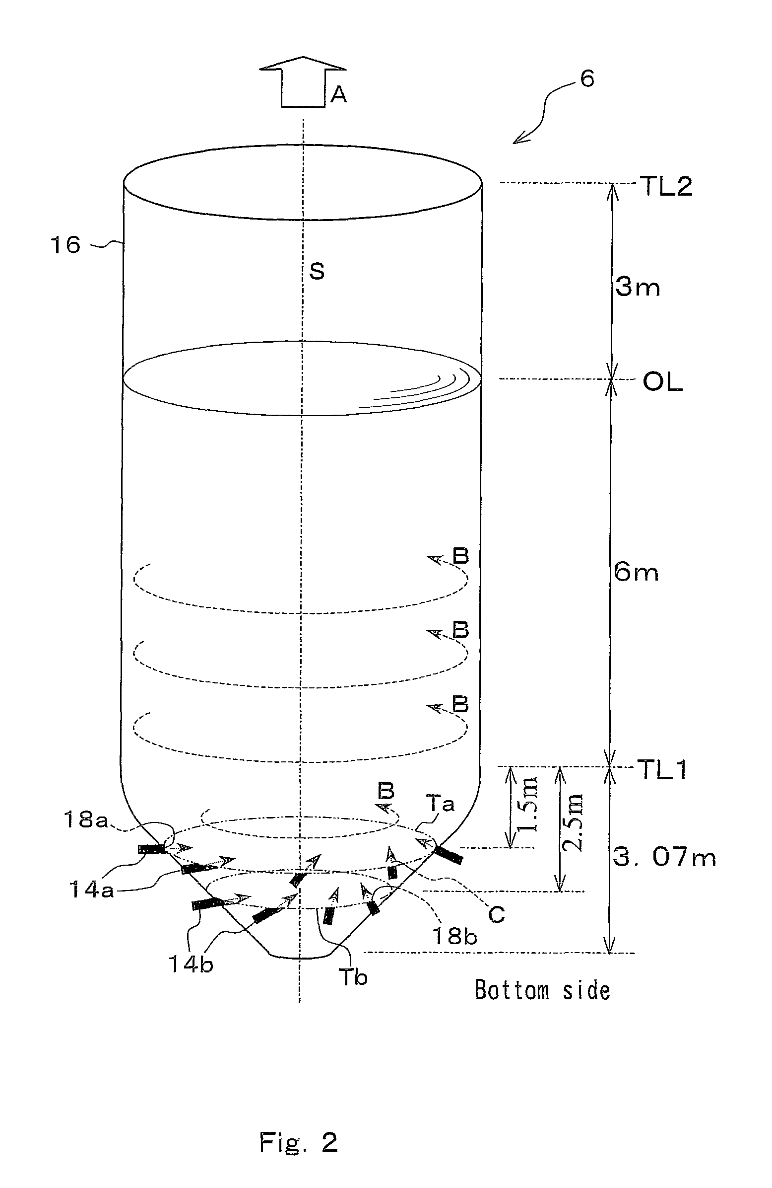
[0085]A reaction vessel having a shape and structure shown in FIG. 2 was used as the reaction vessel of the Example. On the other hand, a reaction vessel having a shape and structure shown in FIG. 14 was used as the reaction vessel of the Comparative Example.

[0086]Further, although there is no dimensional description of the reaction vessel of the Comparative Example in FIG. 14, its dimensions are same as those of the reaction vessel of the Example shown in FIG. 2 (in FIG. 2, OL indicates liquid level, TL1 indicates the lower end of the cylindrical shell and TL2 indicates the upper end of the cylindrical shell).

[0087]Further, other various conditions of dimensions n...


PUM

PropertyMeasurementUnit
facing angleaaaaaaaaaa
temperatureaaaaaaaaaa

Abstract

The suppression of coke adherence in a reaction vessel and cracked gas pipelines at the outlet of the reaction vessel and the prevention of plugging are designed by improving the dispersion of superheated steam inside the reaction vessel to preferable conditions, and pitch having more uniform and higher quality can be produced.A cracking process in which superheated steam is directly contacted with the heavy petroleum oil by blowing the superheated steam into the reaction vessel to be thermally cracked to oil fractions and pitch, wherein the superheated steam is blown into the reaction vessel from the bottom portion thereof so that the superheated steam generates rotational flow around the central axis of the shell of the reaction vessel.

Description

TECHNICAL FIELD[0001]The invention relates to a thermal cracking process for heavy petroleum oil and a thermal cracking reaction vessel (reactor) used for the process, and a thermal cracking facility equipped with the thermal cracking reaction vessel.BACKGROUND ART[0002]Heavy petroleum oil and residual oil having a high content of sulfur such as petroleum asphalt are less valuable because of serious impact on the environment when directly burnt as fuel. Consequently, such heavy petroleum oil (including residual oil; hereinafter the same) is cracked and converted into lighter fractions to be used as various kinds of useful industrial taw materials. As one of such methodologies, the following thermal cracking process is mentioned.[0003]As a process for thermal cracking of heavy petroleum oil, there is a proposed process in which a thermal cracking facility is provided with a cracking furnace and a reaction vessel and the heavy petroleum oil heated in the cracking furnace is introduced...

Claims


Application Information

Patent Timeline
Patent Type & Authority Patents(United States)
IPC IPC(8): C10G9/36B01J10/00
CPCC10G9/36B01J10/00B01J4/002B01J19/24C10G2300/807B01J2219/00006B01J2219/00031B01J2219/1946B01J2219/00121B01J2219/00159B01J2219/00182B01J2219/00247B01J2219/00029B01J2219/00038
Inventor NOMURA, MAKOTOMIMURA, KENICHIMAEKAWA, MUNENORISUZUKI, NAOKOYAGI, KATSUNORI
Owner CHIYODA CORP
Why Eureka
Try Eureka