Eureka AIR delivers breakthrough ideas for toughest innovation challenges, trusted by R&D personnel around the world.

Cooling system for a blower

a technology of cooling system and blower, which is applied in the direction of positive displacement liquid engine, pump, turf growing, etc., can solve the problems of tool breakage, engine cooling and components not working as intended, etc., and achieve the effect of increasing the pressure inside the fan and the blower tube, increasing the pressure, and reducing the pressur

Inactive Publication Date: 2012-09-11
HUSQVARNA AB
View PDF7 Cites 5 Cited by
  • Summary
  • Abstract
  • Description
  • Claims
  • Application Information

AI Technical Summary

Benefits of technology

[0006]The claimed invention eliminates the risk that the engine or components inside the casing will overheat in case of blocked or stopped air stream through the fan or blower tube.
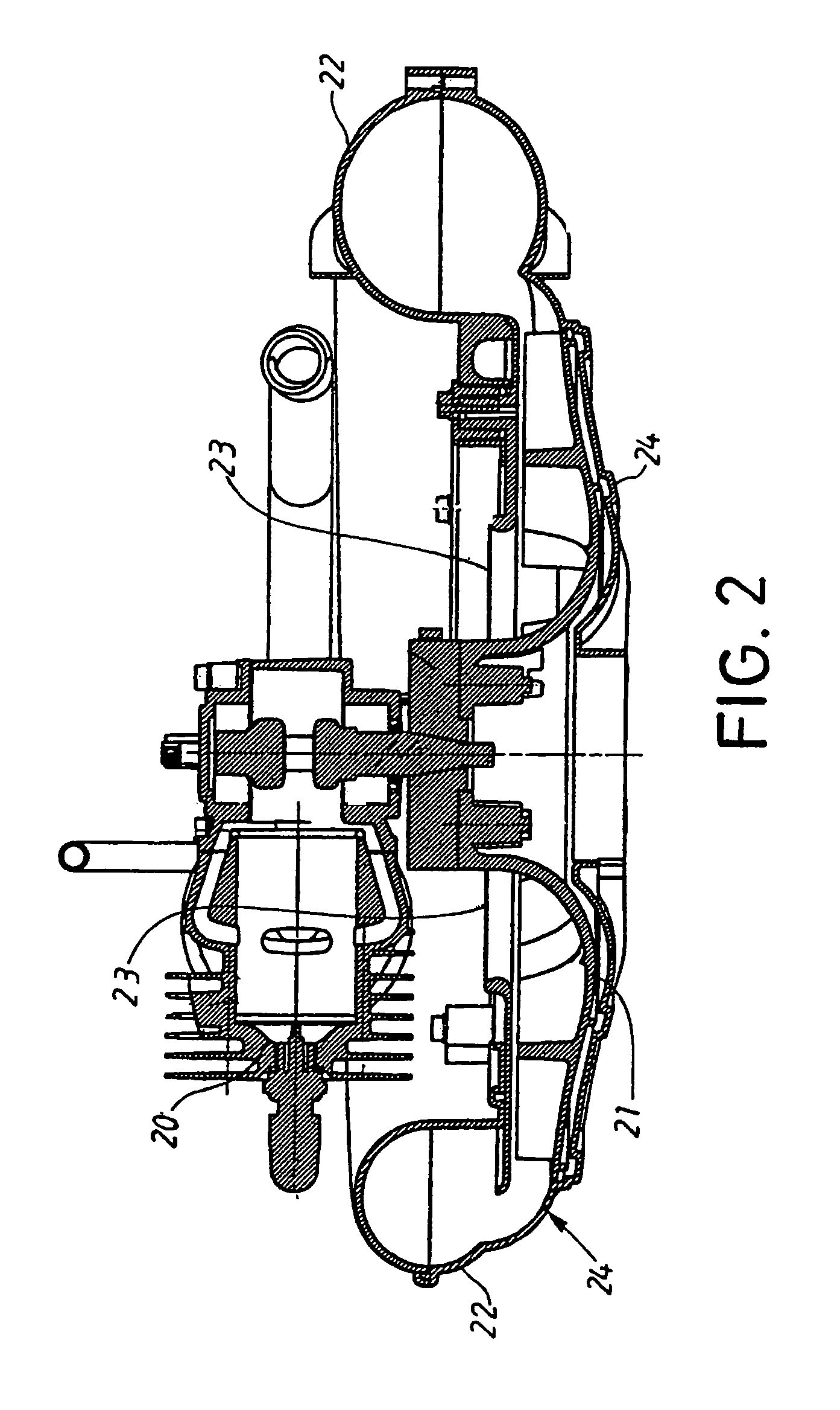
[0008]If the air stream through the fan or blower tube for some reason is blocked will the pressure inside the fan and blower tube increase since no air leaves the system. The increased pressure inside the fan generates an air stream through the opening in the fan housing. The air stream through the opening reduces the pressure inside the fan housing and makes it possible for cool air to enter the fan inlet so that the cooling of the engine and components inside the casing will be maintained even though the blower tube or fan is blocked.
[0009]The opening in the fan housing is placed so that the opening is pointing towards a section of the tool casing where the heated air stream from the opening could be lead out from the casing to avoid that the heated air is circulated inside the casing and increases the temperature inside the casing further. The opening is preferably placed in a position on the fan housing where the pressure inside the fan housing is low during normal running of the blower to minimize the amount of leaking air through the opening during normal running conditions. One preferred position for the opening is close to the periphery of the fan wheel on the side of the fan housing that is facing towards the operator.

Problems solved by technology

This means that no cool air will pass the engine and components inside the casing and the cooling of the engine and components is thereby not working as intended.
If this happens is it a risk that the engine or someone of the components inside the casing will overheat and cause a break down of the tool.

Method used


Image

  • Cooling system for a blower
  • Cooling system for a blower
  • Cooling system for a blower

Examples


Embodiment Construction

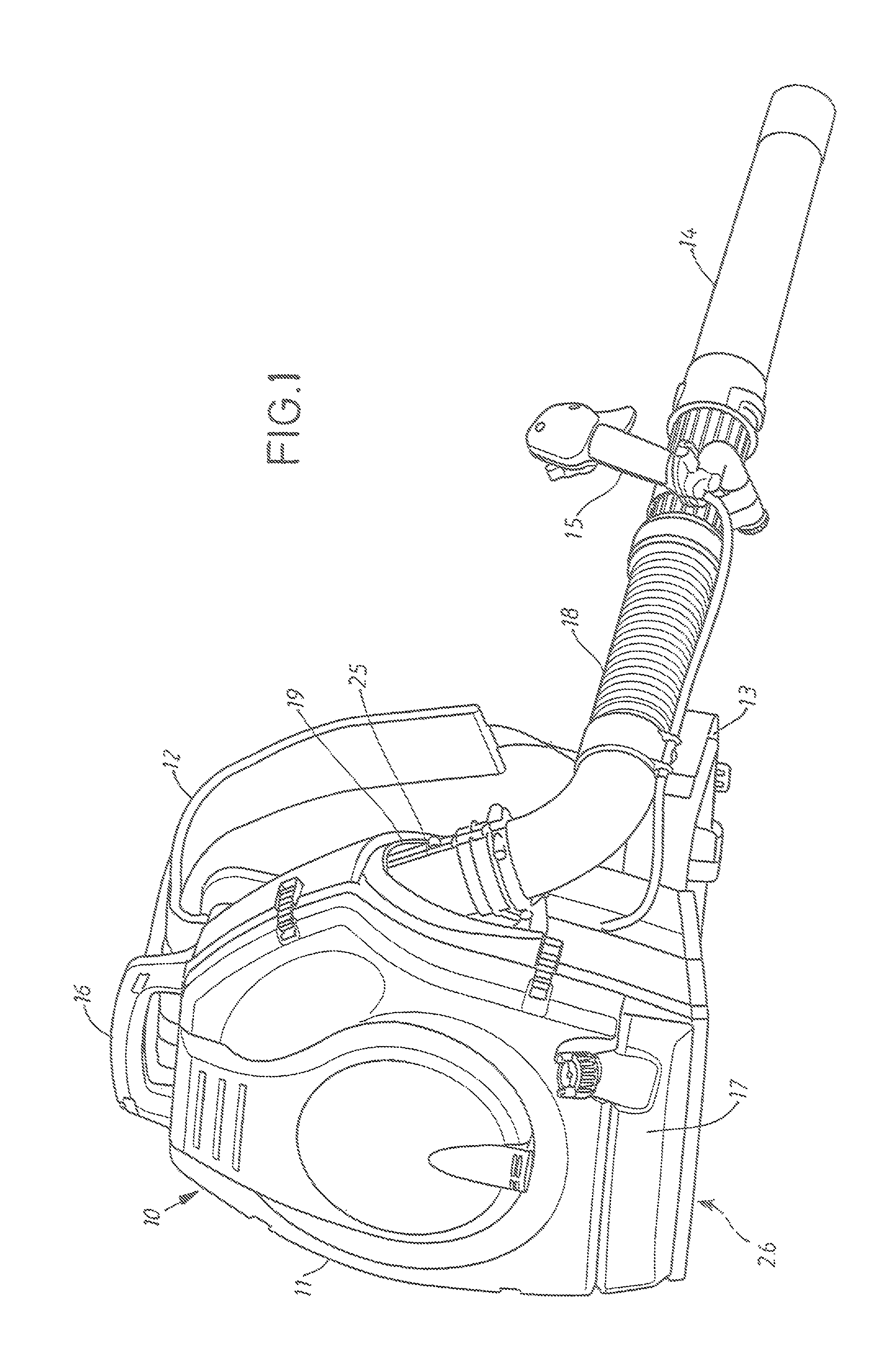
[0014]In FIG. 1 is a blower 10 illustrated. The blower 10 comprises an insulating casing 11 surrounding a tool engine 20 and machinery. The casing 11 is provided with two straps 12 and a waist belt 13 to make it possible for the operator to carry the blower comfortably on the back. A blower tube 14 with a flexible section 18 is extending from an exit opening 19 in the casing 11 placed on the right side of the blower body. The blower tube 14 is placed close to the hip of the operator and the end of the blower tube 14 positioned in front of the operator during use. The operator controls the movement of the blower tube 14 with a handle 15 or a handle bar placed on the blower tube 14. Some blowers have a handle 15 provided with a lever to control the speed of the engine 20. On the topside of the casing 11 is a handle 16 placed to facilitate transports and movements of the blower 10 when it not is placed on the back of the operator and in the lower section of the blower 10 is a fuel tank...


PUM


Abstract

Arrangement in a blower including at least an engine and a fan, the fan includes a fan housing enclosing a fan wheel and a fan inlet. The engine and fan are surrounded by a casing provided with an air inlet to let air in to the fan inlet placed inside the casing. The air stream from the air inlet in the housing to the fan inlet cools the engine and components inside the casing before it enters the fan inlet and leaves the blower via a blower tube. The fan housing is provided with an opening (31) placed in the fan housing so that air is allowed to leave the fan in case of blocked air stream in the fan outlet or blower tube.

Description

BACKGROUND OF THE INVENTION[0001]The claimed invention relates to an arrangement in a blower comprising at least an engine and a fan. The fan comprises a fan housing surrounding a fan wheel, a fan inlet and a fan outlet. The engine and fan are surrounded by a casing provided with an air inlet to let air in to the fan inlet placed somewhere inside the casing. The air stream from the air inlet in the casing to the fan inlet cools the engine and components inside the casing before it enters the fan inlet and leaves the blower via a blower tube.[0002]Engine powered blowers are frequently used for different kinds of work outdoor. The number of areas where blowers are used are increasing. In many areas are blowers replacing traditional brooms since a blower is an efficient and time saving tool for cleaning of large areas such as parking places, pavements and lawns.[0003]In order to reduce the sound emitted from the tool does an insulated casing surround the engine and related components i...

Claims


Application Information

Patent Timeline
IPC IPC(8): F04B17/00F04B35/00F04B39/02F04B39/06F04D25/02F04D27/02F04D29/42
CPCF04D25/02F04D27/009F04D29/4246A01G20/47
Inventor KAGEBACK, MIKAELLARSSON, ANDREASMALMQVIST, LARSHEDLUND, ANDREASNORINDER, LOTTASJOGREN, ANNAJAKOBSSON, ANDERS
Owner HUSQVARNA AB
Why Eureka
Eureka Blog
Learn More