Surface-tolerant RFID transponder device
a transponder device and surface technology, applied in the direction of antenna details, instruments, antennas, etc., can solve the problems of no longer applicable to any surface material, the transponder card attached to a metal plate will not work properly, etc., to reduce the eddy current and prevent the effect of resonance frequency
- Summary
- Abstract
- Description
- Claims
- Application Information
AI Technical Summary
Benefits of technology
Problems solved by technology
Method used
Image
Examples
first embodiment
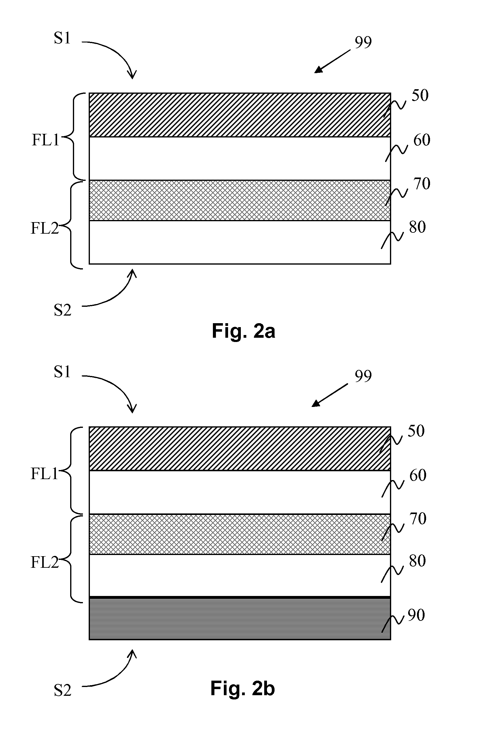
[0062]FIG. 2b shows a schematic cross-sectional view of part of an RFID carrier assembly for an RFID chip according to the invention.
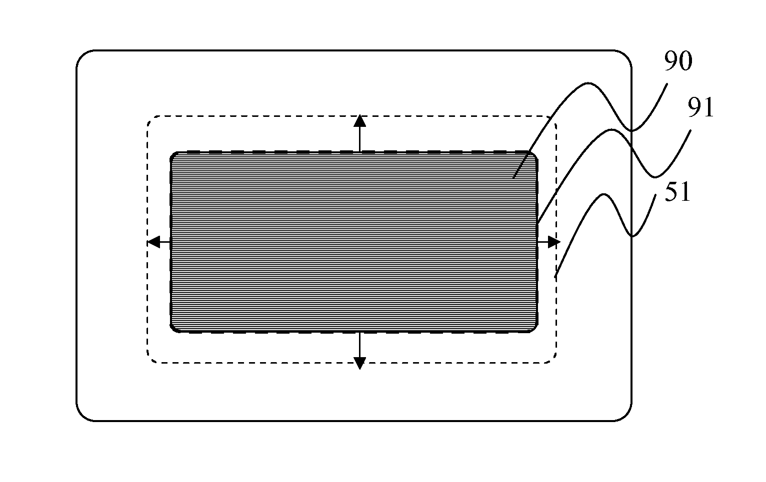
[0063]This figure will be discussed in as far as it differs from FIG. 2a. At the attachment side S2 of the RFID carrier assembly 99 there is provided an electrically conductive shielding layer 90. In this example the shielding layer comprises copper (may be referred to as copper backplane). A typical thickness is 18 μm or 35 μm in case of copper. A minimum thickness is in the order of 2 μm, which may be producible with galvano-antenna technology. As already mentioned the purpose of the shielding layer 90 is to make the detuning effect of the RFID transponder less dependent from the environment, i.e. to make the RFID transponder suitable for being used on different surfaces having different materials, even though the RFID transponder has only been optimized for once specific situation. The first substrate layer 60 and the second substrate layer 70 may c...
second embodiment
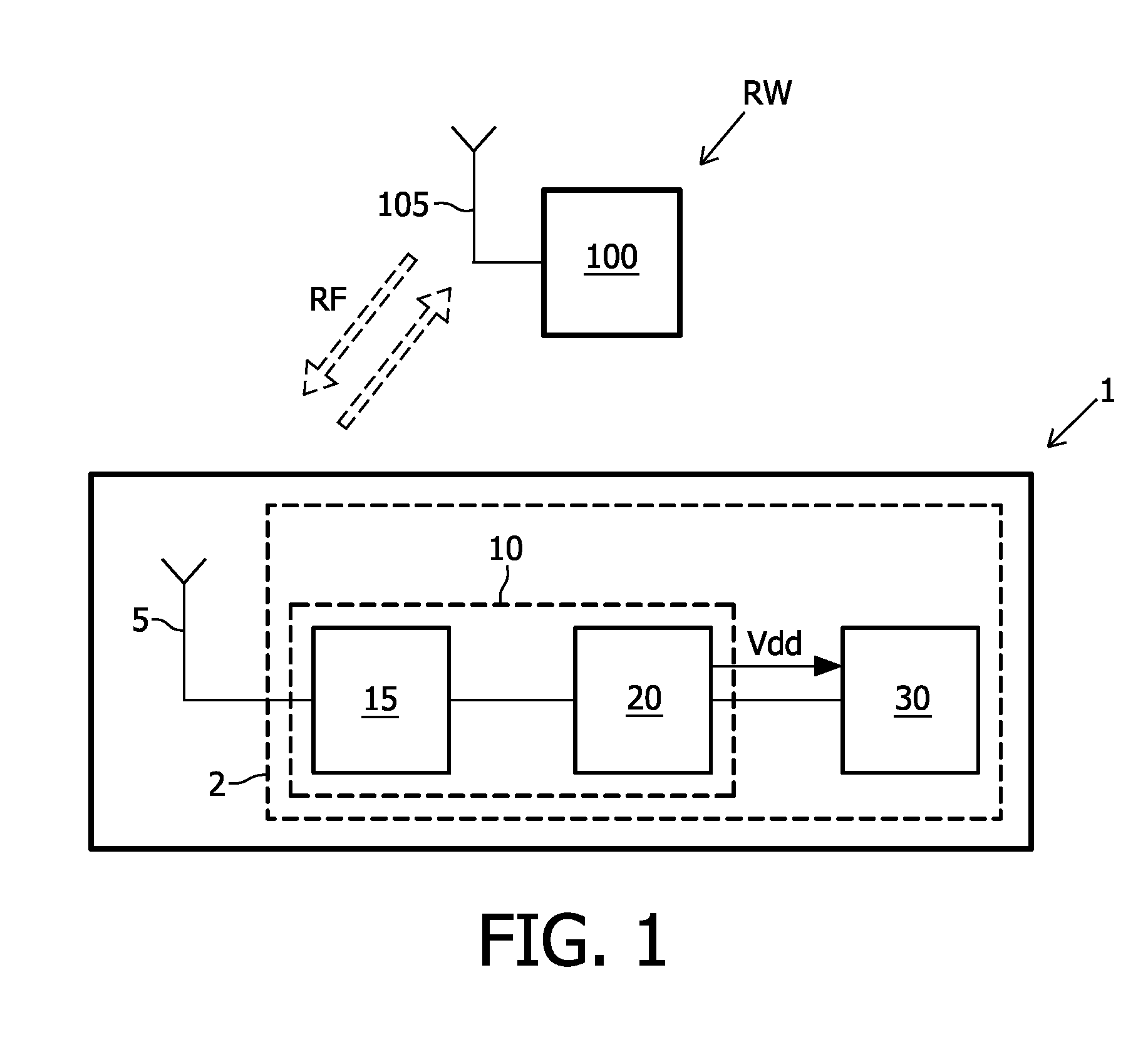
[0066]FIGS. 4a to 4c illustrate schematic transparent layout views of an RFID transponder device according to the invention. FIG. 4a shows a transparent layout view of the RFID transponder device. It shows the antenna 50 which comprises a number of loops and ends up into a first antenna terminal T1 and a second antenna terminal T2. The antenna terminals T1, T2 are configured for being connected with pins of an RFID transponder chip 2. FIG. 4a also shows an outer contour 51 of the antenna 50. FIG. 4b shows a transparent layout view of the RFID transponder device comprising the magnetic layer 70. The magnetic layer 70 has an outer contour 71 which fully encloses the outer contour 51 of the antenna. The advantage of this embodiment is that the magnetic flux is better confined within the magnetic layer 70 and guided in between the antenna layer and the object onto which the transponder is provided. The more the outer contour 71 of the magnetic layer 70 extends beyond the contour 51 of t...
PUM
 Abstract
Description
Claims
Application Information
 - R&D
- Intellectual Property
- Life Sciences
- Materials
- Tech Scout
- Unparalleled Data Quality
- Higher Quality Content
- 60% Fewer Hallucinations
Browse by: Latest US Patents, China's latest patents, Technical Efficacy Thesaurus, Application Domain, Technology Topic, Popular Technical Reports.
© 2025 PatSnap. All rights reserved.Legal|Privacy policy|Modern Slavery Act Transparency Statement|Sitemap|About US| Contact US: help@patsnap.com


