Retractor device

a technology of a retractor and a lid is applied in the field of retractors, which can solve the problems of wide operating window closing suddenly and unexpectedly, affecting the safety of patients, so as to avoid uncomfortable pressure points in the patient's brows or cheeks, avoid contributing to the risk of ptosis or drooping lids, and stiffen the devi

Inactive Publication Date: 2012-09-04
KROLMAN ARTHUR M M
View PDF23 Cites 26 Cited by
  • Summary
  • Abstract
  • Description
  • Claims
  • Application Information

AI Technical Summary

Benefits of technology

[0010]When the retractor device is used as an eye speculum and inserted under the eyelids, each eyelid is constrained in the retainer space formed between the tongue blade and the posts. The spring force of the hinge holds the upper and lower eyelids apart. These posts are approximately the same height as the vertical dimension of the tongue blade. The posts have the advantage that they do not obstruct the operator's view of the tongue, while the retractor device is being inserted into position under the eyelid, as does the solid upper blade that is provided on many conventional devices. The ends of the posts have a ball tip or a knob to avoid uncomfortable pressure points in the patient's brow or cheek or to avoid contributing to the risk of ptosis or droopy lid. The retainer space also serves as an eyelash deflector, i.e., to hold the viewing or operating window free of eyelashes and to prevent the eyelashes from coming into contact with the eyeball.
[0011]A plurality of anti-torque arches are provided along the outer walls of the arms and the hinge. These arches serve to stiffen the device, yet allow flexibility at the live hinge. They also serve to increase the lateral stability of the two arms, that is, they prevent the arms from moving apart laterally relative to one another. For example, it is sometimes the case that the tissue below the eye is swollen and, as a result, exerts a greater force on the arm under the lower eyelid than the upper eyelid exerts on the arm under that eyelid. This force imbalance urges one of the arms to move in a lateral direction relative to the other arm. If unrestrained with regard to lateral movement, the unequal forces on the two arms may result in a torque on the retractor device that can be strong enough to flip the device out from under the eyelids, in which case, the wide operating window closes suddenly and unexpectedly. This may result in catastrophic failure of the ophthalmic procedure. In the embodiment designed as an eye speculum, the retainer space, i.e., the eyelash deflector, extends up to 112 mm outward at a right angle to the arms, to provide sufficient space to accommodate the eyelid. Pressure from the eyelids against the eyelash deflectors exerts a torque on the arms of the retractor device. Several features of the inventive device counteract this torque. The spring hinge applies a force against the eyelash deflectors, to hold open the operating window. The anti-torque arches nearest the tongue blade serve to counteract the torque exerted by the eyelids. In the absence of these anti-torque arches, the opposing eyelash deflectors would twist inward toward one another and, as the more upright tongue blade edge scraped the eyeball, the speculum would be rejected. This, too, could result in catastrophic failure of the ophthalmic procedure. Finally, the plurality of arches serves as an ergonomic grip that allows the surgeon to compress the eye speculum for insertion, without it sliding out from between the fingers and without the fingers slipping down toward the blades.
[0012]The live hinge of the retractor device according to the invention provides sufficient force to hold the eyelids apart. Depending on the intended use of the device according to the invention, however, it may be desirable to include means for bracing the retractor device open. A bracing leg and positioning means may be incorporated into the device, for example, on the inside walls of the two arms. It may sometimes be necessary to secure the retractor device to an open position. For example, the forces exerted by the material being held apart by device may be strong enough to urge the device toward a closed position. Using the device as an eye speculum, this can sometimes be the case with cadaver lids, when a technician requires a very wide operating window in order to excise a donor corneal disk greater than 18 mm diameter. Such large diameter disks are required for subsequent placement on an artificial chamber for preparation of endothelial keratoplasty grafts, for example. The brace means counteracts these forces and holds the eye speculum open to the desired position. The proximal end of a bracing leg is disposed on the inner wall of one arm and a series of ridges provided on the inner wall of the opposite arm. The distal end of the bracing leg may be snapped into position between any two adjacent ridges. This prevents the pressure from the eyelids from moving the arms of the speculum closer together, and thus, allowing the eyelids to close. The eye speculum may be held open to a greater or lesser degree, depending on where in the series of ridges the end of the bracing leg is snapped into place. The closer the bracing leg is secured toward the hinge, the wider the device is urged open.

Problems solved by technology

This force imbalance urges one of the arms to move in a lateral direction relative to the other arm.
If unrestrained with regard to lateral movement, the unequal forces on the two arms may result in a torque on the retractor device that can be strong enough to flip the device out from under the eyelids, in which case, the wide operating window closes suddenly and unexpectedly.
This may result in catastrophic failure of the ophthalmic procedure.
This, too, could result in catastrophic failure of the ophthalmic procedure.

Method used


Image

  • Retractor device
  • Retractor device
  • Retractor device

Examples


first embodiment

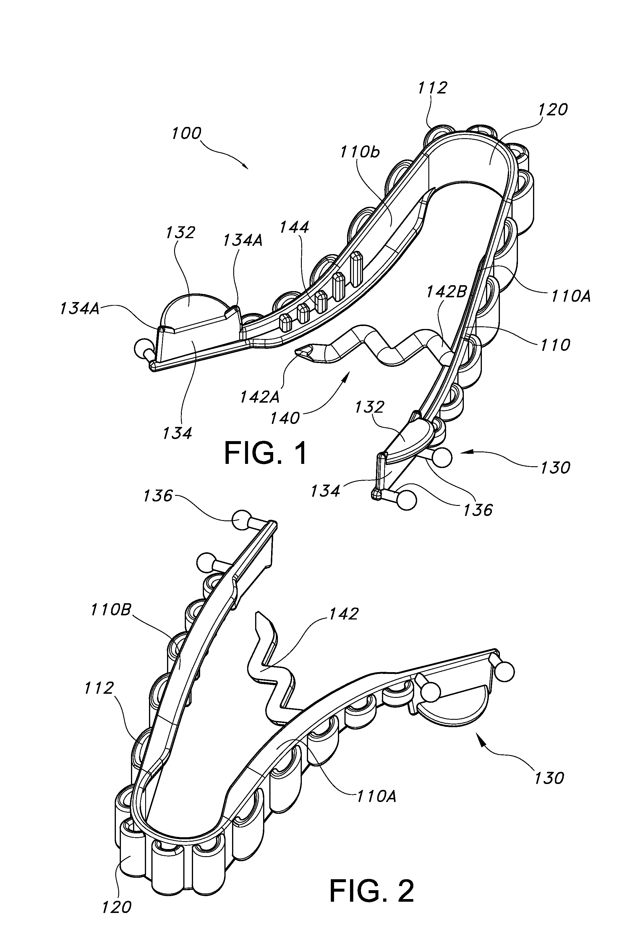
[0030]FIGS. 1 and 10 show perspective views of two embodiments of a retractor device according to the invention. The first embodiment is a retractor device 100 with a bracing means and the second a retractor device 200 without bracing means. Common to both embodiments 100 and 200 is a single-piece molded construction that provides economic advantage as well as improved functional design over conventional retractor devices.

[0031]FIGS. 2-9 illustrate various features of the first embodiment retractor device 100. The retractor device 100 has an overall U- or V-shape and is a unitary molded piece comprising a pair of arms 110, a hinge 120, retraction means 130, and anti-close brace means 140, whereby all of the elements 110-140 are integrated into the molded construction of the piece.

[0032]The pair of arms 110 include arms 110A and 110B. Each arm 110A, 110B terminates at its respective distal or free end in the retraction means 130; the opposite ends of the arms 110A, 110B are joined to...

second embodiment

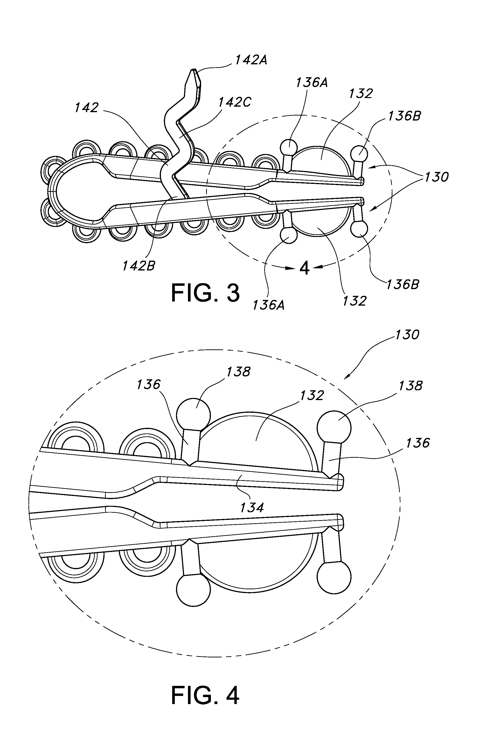
[0038]The terms “upper” and “lower”, as used to designate the arms 110, are relative terms, depending on whether the retractor device 100 / 200 is being inserted in the right or left eye. In other words, the arm 110A as shown in FIGS. 1 and 2 is an upper arm when the device is inserted into the left eye of a person and a lower arm when inserted into the right eye. The arms 110 are squeezed together to bring the retraction means 130 on each arm close to the other, as shown in FIG. 3. The tongue blade 132 of the upper arm is inserted under the upper eyelid and the tongue blade 132 of the lower arm inserted under the lower eyelid. The retainer posts 136A and 136B provide the advantage that they do not obscure the greatest part of the window or restrict unnecessarily the angle of insertion during the insertion step. The area of insertion is further increased in the second embodiment, with the curved geometry of the deflector 234. This improves the ability of the surgeon or technician to v...


PUM


Abstract

A retractor for ophthalmic procedures and other uses is disclosed. The retractor is a U-shaped body formed by two arms and a live hinge, with a retracting means at the distal end of each arm. The retracting means includes a tongue blade for insertion under an eyelid, a deflector for retracting the eyelid, and two ball-tipped posts that extend away from the tongue blade and prevent eyelid or eyelashes from obscuring the window opened up by the retractor. The hinge is also an adjustable biasing spring that biases the distal ends of the arms to an open position. Anti-torque arches are provided on the outer wall of the body. A brace may be provided on the retractor, to fix the device to a desired position.

Description

BACKGROUND INFORMATION[0001]1. Field of the Invention[0002]The invention relates to a retractor for holding an aperture open, and particularly an eyelid speculum.[0003]2. Discussion of the Prior Art[0004]A device referred to as an “eye speculum” or a “retractor” is frequently used for various medical procedures on the eye, to hold the upper and lower eyelids apart, in order to have access to the eye. Conventional eye specula include rigid, hinged metal devices, some withs an anti-close locking wheel to fix the speculum to a desired open position, as well as wire devices that have a live hinge, without any means for fixing the speculum to a particular open position.[0005]Understandably, the hinged metal devices with the anti-close locking wheel are expensive to manufacture. They have multiple parts that require assembly, some of the parts require precision machining, etc. On the other hand, the wire devices with the live hinge can be difficult to use for a number of reasons. It is po...

Claims


Application Information

Patent Timeline
IPC IPC(8): A61B1/32
CPCA61B17/0231A61B17/2833A61B19/08A61B46/00
Inventor KROLMAN, ARTHUR M. M.
Owner KROLMAN ARTHUR M M
Why Eureka
Try Eureka